24
402s Ovens Part. N
o.
32Z3539 Issue 5
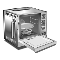
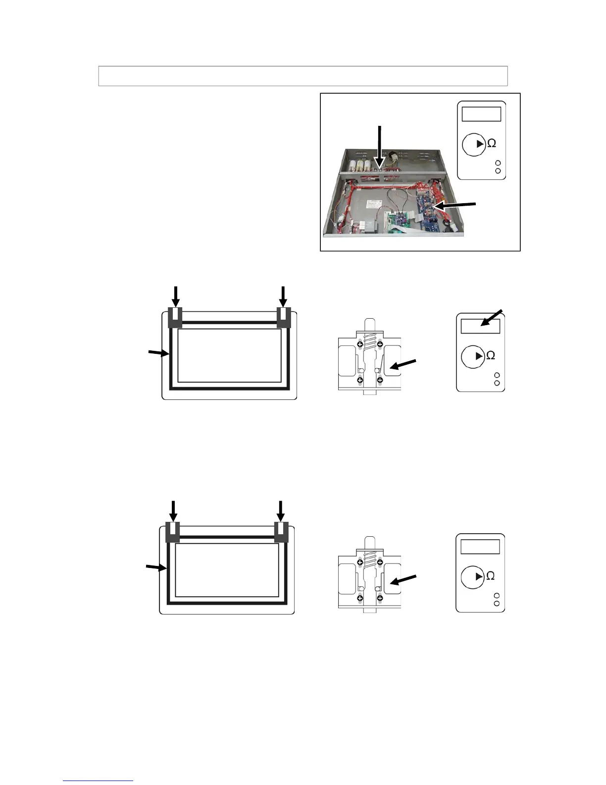
PROCEDURE FOR DOOR INTERLOCK ADJUSTMENT AND TEST 3
3
Remove the 4mm spacers and open and close
the door 2 or 3 times to allow the parts to work
together.
Set a Multimeter Resistance [ Ω ] and connect
the meter to Fuse F4 and Tag 7 on the Relay
PCB Board.
Check that microswitches SW2 and SW3 are in the CLOSED [ON] position and
the Multimeter reads a minimal resistance.
If the meter reads Open Circuit, remove the 2mm spacers and repeat steps 1-4
moving the switch assemblies very slightly further down.
This procedure may need to be repeated several times to achieve a satisfactory
arrangement.
Fuse 4
Tag 7
4
To confirm the oven operates at a 2mm door open position.
Replace the 4mm spacers with the two GREEN 2mm Spacers.
GREEN Spacers
SW3 & SW2
CLOSED
0.1
Open Circuit
RED Spacers
The meter should now read open circuit,
if not repeat steps 1 & 2 adjusting the switch assemblies slightly
upwards, ensuring the Microswitches are in the OPEN [OFF] position.
SW3 & SW2
OPEN
Replace the RED 4mm spacers on the door
and over the corners of the seal as before.
Door
Seal
Door
Door
Seal
Door
 Loading...