23
402s Ovens Part. N
o.
32Z3539 Issue 5
PROCEDURE FOR DOOR INTERLOCK ADJUSTMENT AND TEST 2
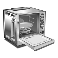
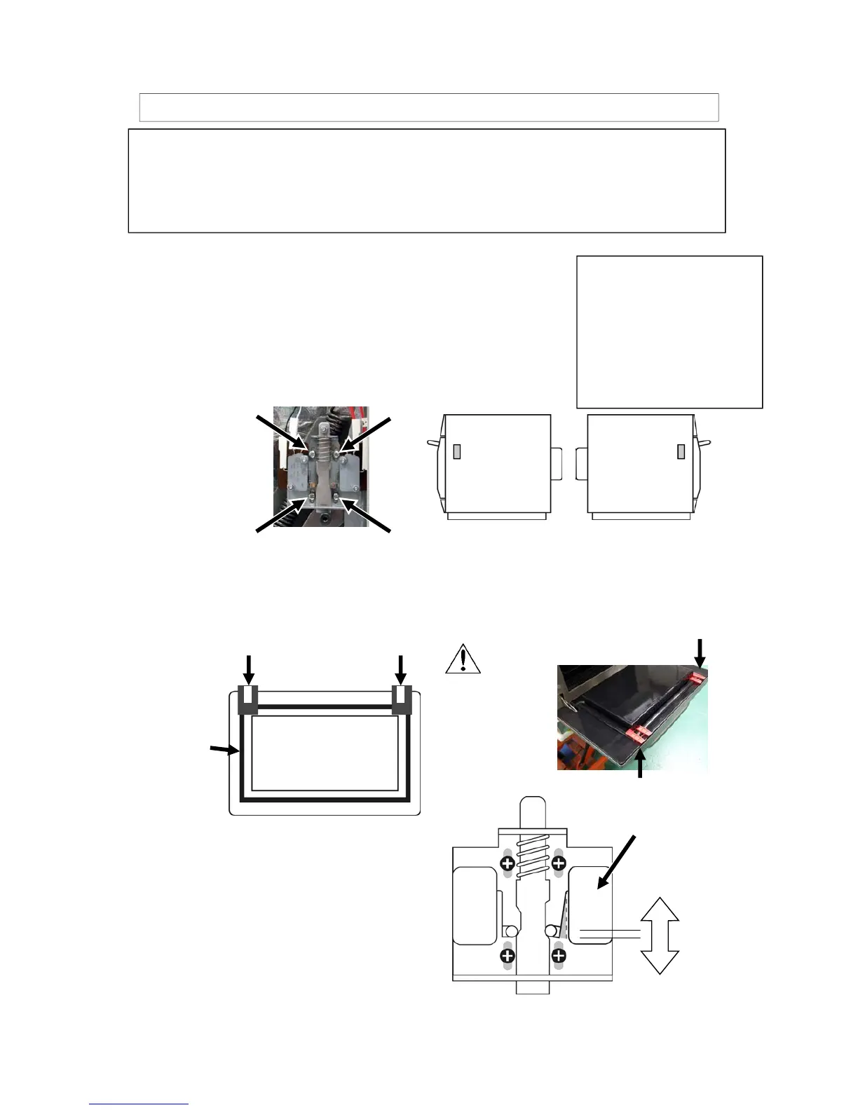
Release the 4 screws retaining each microswitch assembly
The purpose of this procedure is to set the interlock so that when the door
is opened more than 4mm the Oven microwave circuit is switched OFF.
The door closed position [Microwave circuit ON] is actually set with a 2mm
opening to allow for heat expansion when the oven is operating at full
temperature.
WARNING
Before adjusting the microswitch assemblies ensure that the oven has been isolated from
the electrical supply and discharge the HT Capacitors.
Please note the terminals on the microswitches remain live when the oven is switched off,
so complete isolation is essential.
WARNING
DO NOT set the microswitch
assembly at the bottom of the
adjustment slots as this would
result in the microwave circuit
operating for a much larger door
opening distance and cause
potential microwave leakage from
the oven.
1
To set Microswitches SW3 & SW2 to OPEN
[OFF] at a door opening with a 4mm gap:
On the LHS of the oven, press down on the
switch assembly to set SW3 to just click
CLOSED and then allow the assembly to
move 1-2mm to just allow the switch to
return to the OPEN position and tighten all 4
screws.
Repeat the procedure on the RHS of the
1-2mm
SW3 LHS
SW2 RHS
CLOSED
OPEN
Spacer
Position the door open with a 4mm gap:
Place the two RED 4mm Spacers over the door seal at the top of
the door on each side at the corner and carefully close the door
ensuring the spacer is on the door seal.
2
RED Spacers
Smooth
side of
spacer to
door seal
Door
Seal
Door
Spacer
 Loading...