List of Figures v
List of Figures
Figure 1 Meru Wireless LAN (WLAN) ..................................................................................1
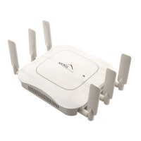
Figure 2 AP200 .......................................................................................................................3
Figure 3 AP100 .......................................................................................................................3
Figure 4 AP100-P (Plenum Rated) .........................................................................................4
Figure 5 Attaching an Antenna to the AP100 .........................................................................10
Figure 6 Attaching the Ethernet Cable to the AP100 ..............................................................10
Figure 7 AP100-P Plenum Installation Items .........................................................................12
Figure 8 Light-Pipe Extender Attached to Bracket .................................................................12
Figure 9 AP100-P Installed Above Ceiling Tile .....................................................................14
Figure 10 RJ-45 LEDs ............................................................................................................14
Figure 11 Access Point 100 Status LEDs ...............................................................................15
Figure 12 AP200 Mounting Bracket .......................................................................................20
Figure 13 AP200 Antenna Connection ...................................................................................23
Figure 14 AP200 Connector Panel ..........................................................................................24
Figure 15 AP200 Bracket ........................................................................................................25
Figure 16 Aligning the AP200 with the Bracket .....................................................................26
Figure 17 Sliding the AP200 into the Bracket ........................................................................26
Figure 18 Mounting the AP200 to a Suspended Ceiling Rail .................................................27
Figure 19 Mounting the AP200 Above a Suspended Ceiling .................................................29
Figure 20 Box Hanger Mounting Bracket Holes ....................................................................29
Figure 21 Attaching the Mounting Bracket to the Box Hanger ..............................................30
Figure 22 RJ-45 LEDs ............................................................................................................31
Figure 23 AP200 Status LEDs ................................................................................................32
 Loading...