20
During an alarm cycle there is either a negative command for controlling the original relay on the BROWN wire or a
supplementary relay for the horn or a Pager.
The negative command can be the continuous or alternating type depending on what was selected in the accessory
functions programming table.
For the di erent types of connection please comply with the indications given in Figures 18 and 18/A.
Fig. 18 Fig. 18/A
ALARM OUTPUT FOR HORN/PAGER RELAY
NEGATIVE COMMAND POSITIVE COMMAND
When the alarm is activated, a 12 second timed command is given to the PINK/BLACK wire with POSITIVE polarity for
controlling the power window accessory module M2008.
If you wish to activate the alarm without the windows closing, simply press the button on the LED just before
activating the alarm, via the original remote control.
The polarity of the power window module signal can be changed with the portable programmer PDC/CAR ALARM
PROGRAMMER (ABS0889) and a signal can be used with a NEGATIVE polarity which can control, for example, an
original comfort feature.
POWER WINDOW MODULE AND WINDOW UP INHIBITION
Additional modules can be used/disabled temporarily with this alarm, as for the volumetric protection; to
this end, it provides a dedicated positive output for controlling the modules (PINK wire) and an input for the
alarm signal coming from them (YELLOW wire).
AUXILIARY PROTECTION INHIBITION
To disable the auxiliary modules, proceed as illustrated below; activate the +15 car panel 3 times and lock the car with the
original remote control within the next 20 seconds.
The LED ashes very quickly during the immunity time to indicate that the alarm is activated with the volumetric protection
disabled.
AUX
Attention! when you disable the modules the ultrasound volumetric protection is disabled as well, temporarily
+ 15 ON
+ 15 OFF
+ 15 ON
+ 15 OFF
MAX
20 SEC.
+ 15 ON
+ 15 OFF
X 4
= 2 FLASH
= 4 BEEP
X 3
= 1 FLASH
= 3 BEEP
ALARM
POSITIVE
ALARM
INPUT
AUXILIARY MODULES
POSITIVE
COMMAND
YELLOW YELLOW
PINK PINK
SENS.
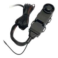
M14/2008
Connection example for
the auxiliary module
Shock Sensor M14/2008
AUXILIARY PROTECTION MODULE
Fig. 19
87
30
86
85
87 30
86
85
+30 o +15
CLACSON
BROWN
+30
ORIGINAL
HORN
CONTROL
MOUNT AN
ADDITIONAL
RELAY IF HORN
IS SUBKEY
ORIGINAL
HORN
RELAY
+30
+
+30 o +15
CLACSON
BROWN
ORIGINAL
HORN
CONTROL
MOUNT AN
ADDITIONAL
RELAY
87
30
86
85