46
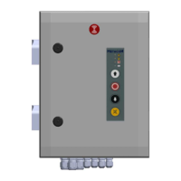
9 (Error) Messages
9.1
Status messages
9.2
Error messages
(for questions: +31 (0) 182 23 15 25 or service@metacon-next.com)
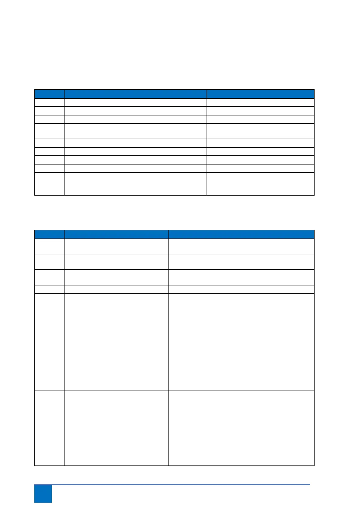
Recommendation/Explanation
E 1.1 Operation open active.
E 1.2 Operation stop active.
E 1.3 Operation close active.
E 1.4 BMC input 1 active/interrupted or not yet reset. Smoke alarm active/short circuit in
cables
E 1.5 Escape button active.
E 1.6 Test function active.
E 1.7 BMC input 2 active/interrupted or not yet reset.
E 1.8 Mute button active.
C.S. Maintenance cycle reached. Perform maintenance on the door and
configure par. 8.5 again. The LED on the
lid will flash red/green alternately.
Recommendation/Explanation
F 1.3 Safety chain drive unit DES. Thermo contact activated. Allow the drive unit to cool
off.
F 1.4 Input for slack cable/pass door contact
activated.
Check cables, pass door/slack cable contact and 5 kΩ
resistor connected to X12
F 1.5 Cable breakage smoke
detector/remove smoke detector
Short circuit in connection cables of detectors; remove
one of the detectors in the chain from the socket.
F 1.6 Input for safety brake activated. Check switching contact and/or cables safety brake.
F 2.0 No safety edge present or safety edge
faulty.
This message is shown if a decision has been made to
automatically detect the safety edge.
This message will appear once if the safety edge is not
detected when starting up the controller; this can be
lifted by fully opening the door.
If a safety edge is connected, make sure it is connected
correctly to X13. The eyes of opto sensors must see
each other when the controller is started. A 1.2kΩ or
8.2kΩ resistor must be present in the safety edge when
starting up the controller. Possibly manually configure
the safety edge type via the menu.
F 2.1 Photocell activated. The photocells have been broken. This could be
attributed to the light beam being broken, a faulty
photo cell and/or an error in the electric circuit.
Check the following if this message persists:
- Has the photocell been correctly aligned and is the
lens clean.
- Is the electric circuit connected to X11. Photocells not
broken; circuit must be connected to X11 (terminals 3
and 4). If photocells are not used, place a wire bridge on
X11 terminals 3 and 4.