13
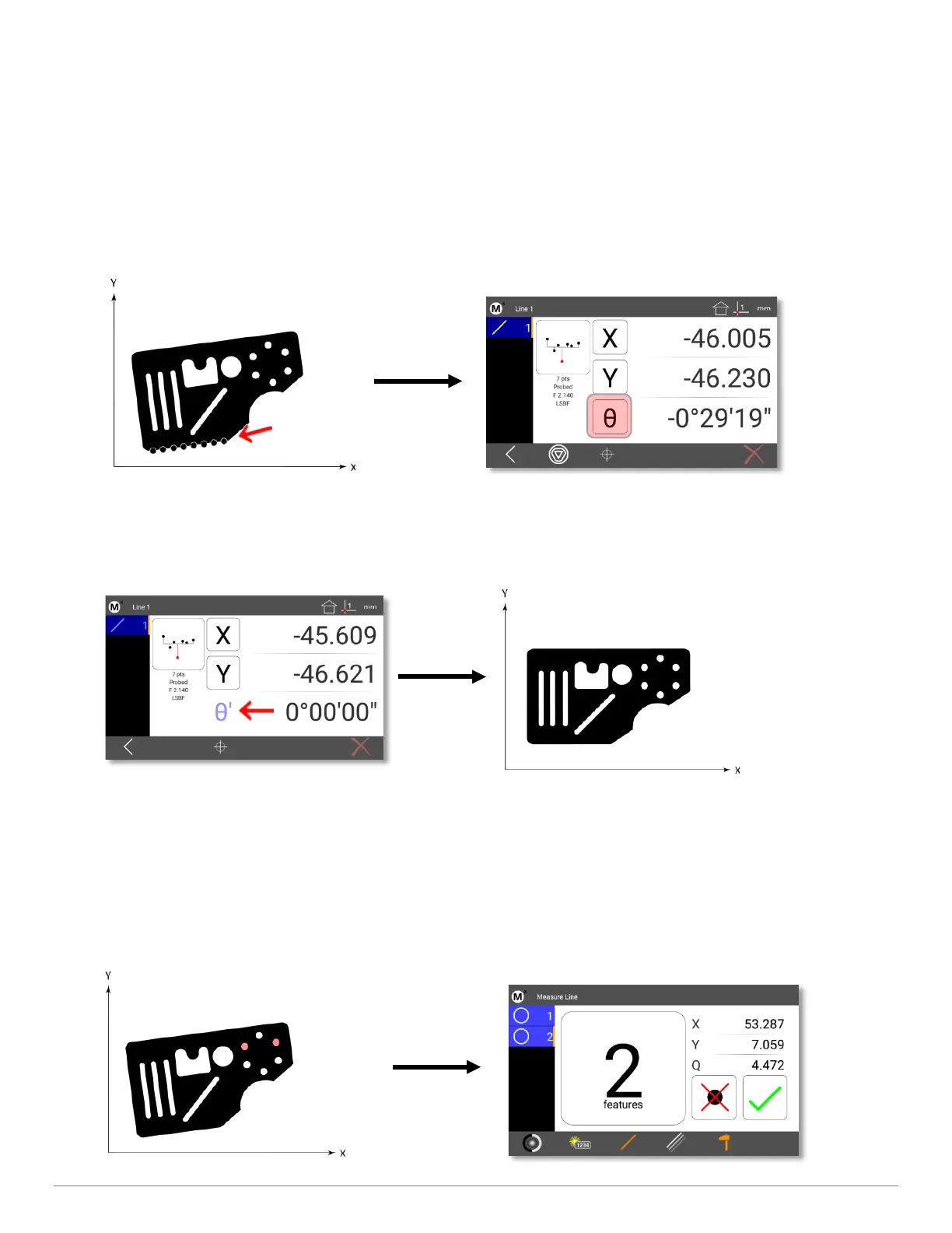
4.3 Performing a Skew Alignment on a Line Feature
To probe a skew alignment line:
• Step 1: Press the Measure Line button.
• Step 2: Probe points well distributed along the entire length of the desired part alignment edge (X axis in the
example below). More points probed on the reference edge will increase measurement accuracy.
• Step 3: Press the “Finish” button to complete the measurement. The line will be shown in the Feature list and
Feature Detail screen.
4 Zero the line angle by pressing the Angle button to align the part to the X axis. The X and Y coordinate button images
will change from X and Y to X' and Y' to indicate that a skew alignment exists. The Angle value label will turn blue and
a (‘) will be added to indicate it is a datum feature.
4.4 Constructing a Skew Alignment Between 2 Circles
A skew alignment line can also be constructed between any two positional features.
To construct a skew alignment line:
• Step 1: Press the Measure Line button.
• Step 2: Select (press) the desired parent features in the Feature list (two circles in this example).