3
1 Introduction
The Mx200 user guide describes the operation of the Mx200 readout. The Mx200 supports manual part positioning and
feature measurement under direct user control. While this guide might include some material that doesn’t apply to your
specific Mx200 configuration, the concepts explained are applicable to all Mx200 systems. For example, Mx200 systems
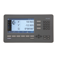
can be 2 or 3 axis systems with X, Y, Z or X, Y, Q axes. This guide will show images of an X, Y, Q axis system.
1.1 Mx200 Readout
The Mx200 is a metrology readout for performing two and three axis measurements. Measurements can be performed
using optical comparators, measuring microscopes and a variety of other crosshair measurement systems. All user
interaction with the software is through the color touchscreen or through the use of softkeys and function keys on the
rubberized keypad.
Features are measured by entering points manually using a simple crosshair probe, or automatically using optical edge
detection. The probes include:
• Simple crosshair
Used for manual point entry.
• Optical edge detection
Identifies the location of a point as the optical crosshair probe crosses an edge. There are two modes, Auto-Mode
where points are immediately entered for use in a feature measurement, and manual edge mode where once a
point is taken, the operator must press enter to “accept” the point for the measurement.
1.2 Prerequisites
Operators are assumed to understand the basics of dimensional metrology.
1.3 Getting Help
Help is available:
• In this guide.
• In the electronic version of this guide accessed from the Help function(“?” Button) in the Mx200 Setup Menu
toolbar.
• From your MetLogix distributor or system provider.
• From our product support page at www.metlogix.com.