Autolab/Electronic load combination
49 | Page
Appendix 2 – Modification of the FRA2 module
By default, the external inputs of the FRA2 modules shipped before July 2009
(revision number 8.0 and lower) can be used to record analog signals in the ± 5 V
range. For some applications, analog signals in the ± 10 V range are required. In
order to be able to record voltages between 5 and 10 V, the FRA2 modules with
revision numbers lower than 8.1 need to have the extended range offset DACs
activated. This requires a simple hardware modification described in this
document. Please contact Metrohm Autolab B.V. (info@metrohm-autolab.com) or
your local distributor in case of any doubts.
The modification described in this document requires the following items:
1. ESD safety kit (see Figure 44)
2. Soldering iron and solder
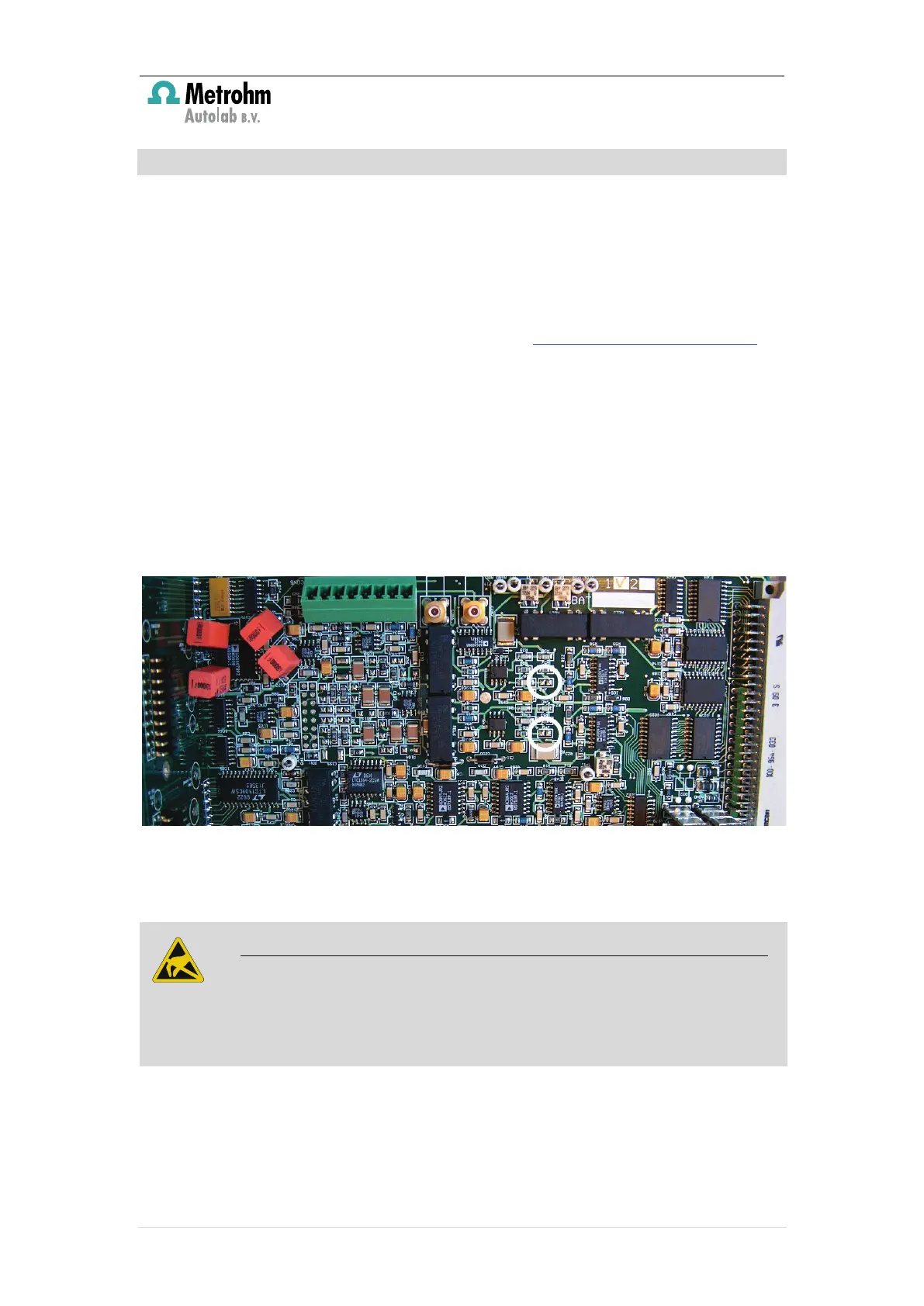
The modification requires soldering
and
of the analog board of the FRA2
module. Figure 44 shows a picture of the Analog board. The two jumpers are
highlighted.
Figure 44 – The FRA2 Analog board (JP2 and JP3 are highlighted)
The two jumpers need to be soldered together.
Remove the FRA2 module from the Autolab frame. To remove the FRA2 module
follow the instructions reported the following documents:
The modification described in this document requires the following items:
Take all the necessary steps to avoid ESD damage to the module by grounding
yourself during the handling of the module and the soldering of the jumpers.
The use of a ESD safety kit is highly recommended.
 Loading...