IMO-R23EN 9
Seats should be in this
position at assembly
Figure 3a
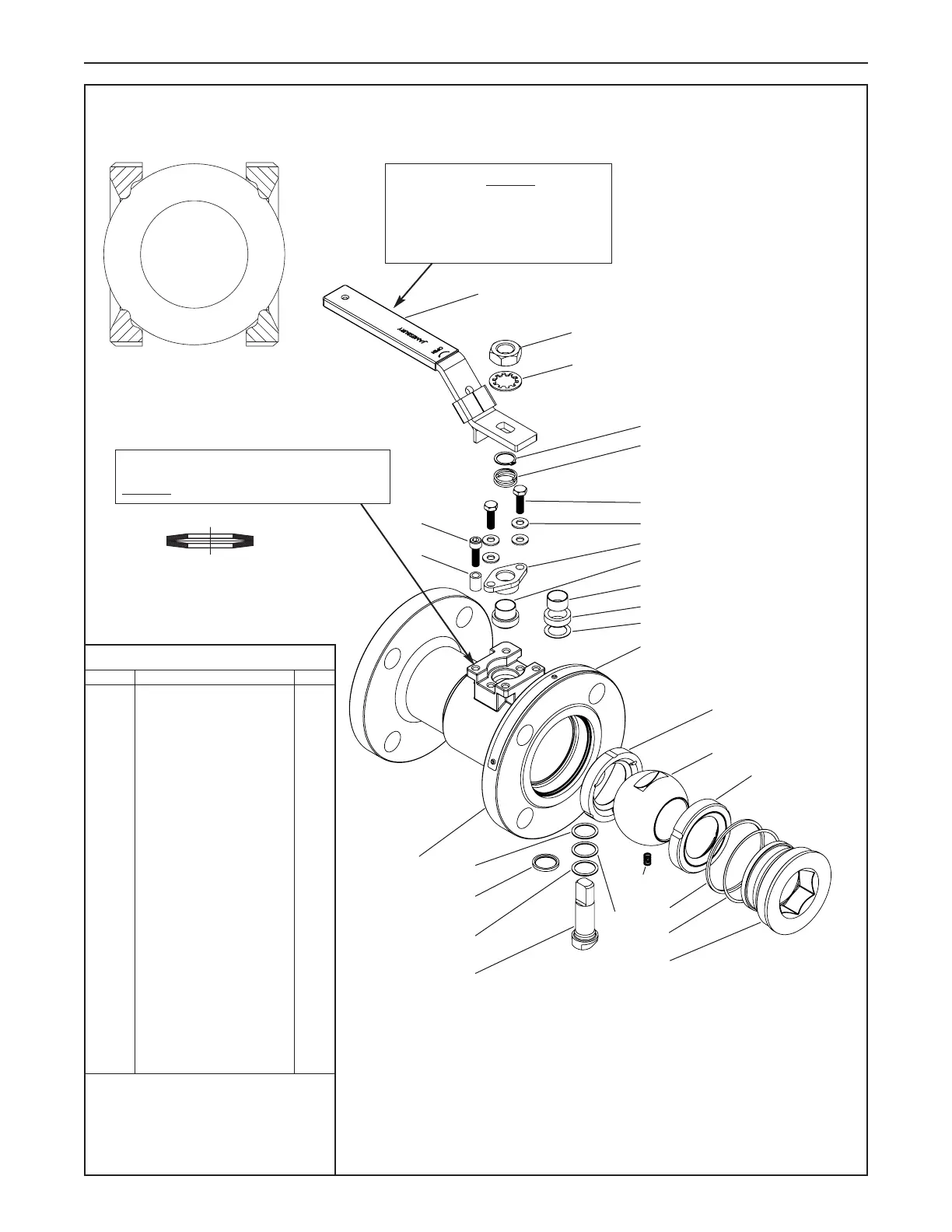
7 EXPLODED VIEW AND PARTS
Proper Disc Spring Orientation
PARTS LIST
ITEM PART NAME QTY
1 Body 1
2 Insert 1
3 Ball 1
4 Stem 1
5 Seat 2
6 Body Seal 1
7* Secondary Stem Seal 1
8 Stem Seal 1
9*** Support Ring 1
10**** Upper Stem Bearing 1
13* Stem Bearing 2
16 Handle Nut 1
17 Handle 1
19 Shakeproof Washer 1
20 Compression Plate 1
22 Identification Tag 1
24** Stem Bearing Non Fire-tite 1
25 Socket Head Cap Screw 1
26 Spacer 1
29 Hex Head Cap Screw 2
31 Disc Spring 4
55**** Anti Extrusion Ring 1
70 Upper Grounding Spring 1
71 Lower Grounding Spring 1
72 Retaining Ring 1
*
Fire-tite
valves only
** Non
Fire-tite
valves only
*** Use Item 9 for 1" and 1-1/2" (DN 25 and 40)
9000, 1-1/2" and 2" (DN 40 and 50) 7000
graphite seals only
****Used for upper graphite stem seals only
Figure 3
Handle (17) MUST be in
this orientation over non-
insert flange when valve is
in the open position.
Stop screw (25) with bushing (26)
MUST
be in this location.
1
16
19
26
25
17
4
24
13
13
70
29
31
20
8
10****
8****
55****
72
22
2
9***
6
3
71
7
5
5
 Loading...