Slurry Pump
WH15AM1AAA0EN_06B.DOC JAN 05-W02
Installation
7/8
45º-60º
D
L
V(m )
3
15s V/Q 2min
<<
Q(m /s)
3
(4 × D) L (10 × D)
<<
d
F
S
h
H
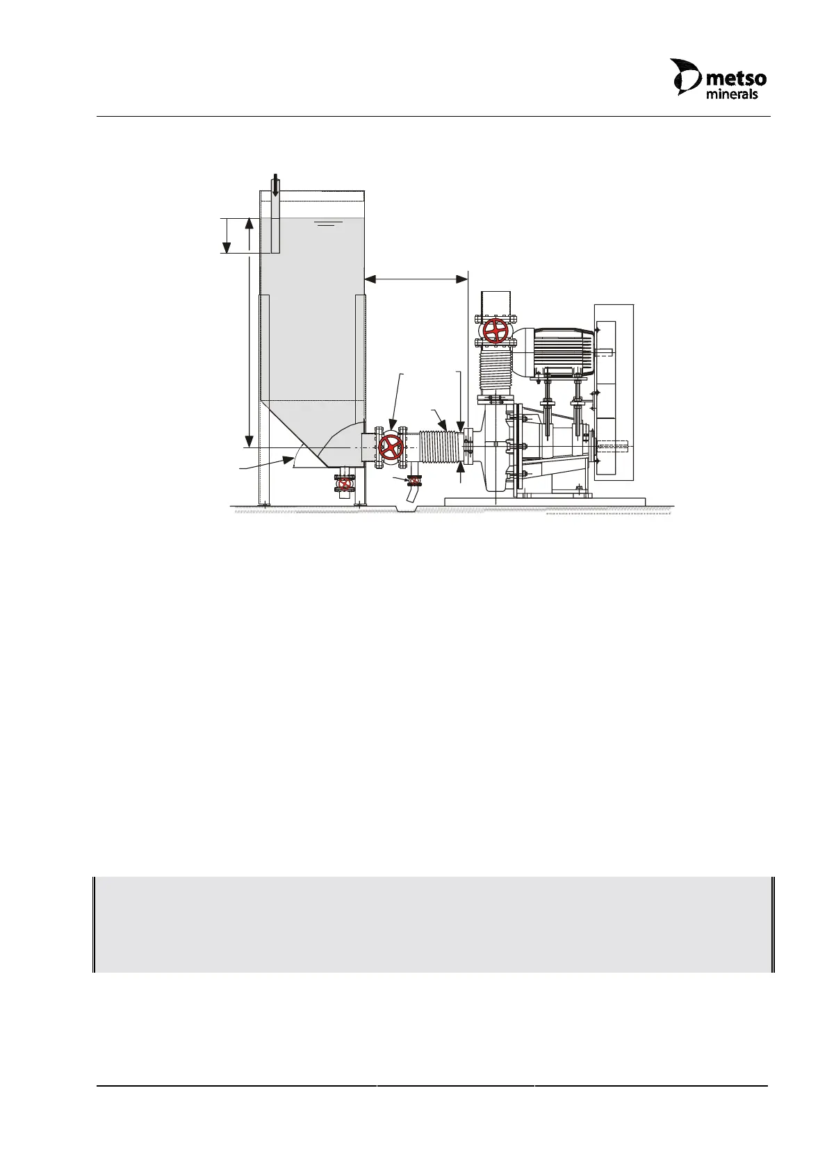
Figure 6.5-1 Recommendations for pipework layout
The pump is NOT self-priming, which means that the pump case must be full of liquid
before the pump is started. Additionally, take note of the following (see also Figure 6.5-1):
• Sump bottom should have an angle of 45º. Fast settling particles may require up to
60º.
• Sump feed (h) should be below the sump liquid surface to avoid air entrainment.
Allowing the pump to draw air will drastically reduce the useful life of the hydraulic
parts.
• Sump volume should be as small as possible. Slurry ‘Retention Time’ is the relevant
parameter for determining the size of the sump. It ranges between 15 seconds and 2
minutes for slurries containing coarse particles and fine particles, respectively.
• Separate sumps are preferred for standby pump installations. This will avoid settling
out in the standby pump when not in use.
• For slurry applications, ensure a steady, uniform feed to the pump, where practicable.
• Install the pump as close as possible to the sump.
• Keep the length of suction pipe and the number of bends in the pipework to the
minimum practicable. Use reinforced flexi-pipes (F) to connect to inlet and outlet.
NOTE: INLET PIPE SHOULD, HOWEVER, HAVE A STRAIGHT LENGTH (L), AT LEAST, 4 TIMES ITS
DIAMETER TO ENSURE FAVOURABLE FLOW CONDITIONS INTO THE PUMP. IF A VALVE (S) IS
FITTED ON THE INLET SIDE, IT MUST BE FULLY OPEN WHEN THE PUMP IS RUNNING AND
SHOULD HAVE A STRAIGHT FLOW PATH OF THE SAME AREA AS THE CONNECTED PIPE.
SUCTION PIPES WHICH ARE LONGER THAN 10 TIMES THE DIAMETER SHOULD BE AVOIDED.
• Sump level (H) should be 6 times pump inlet diameter (D) when measured from the
centre line of pump.
• The diameter of the inlet pipe should be the same as, or larger than, the pump inlet
diameter.
 Loading...