35
Configuration
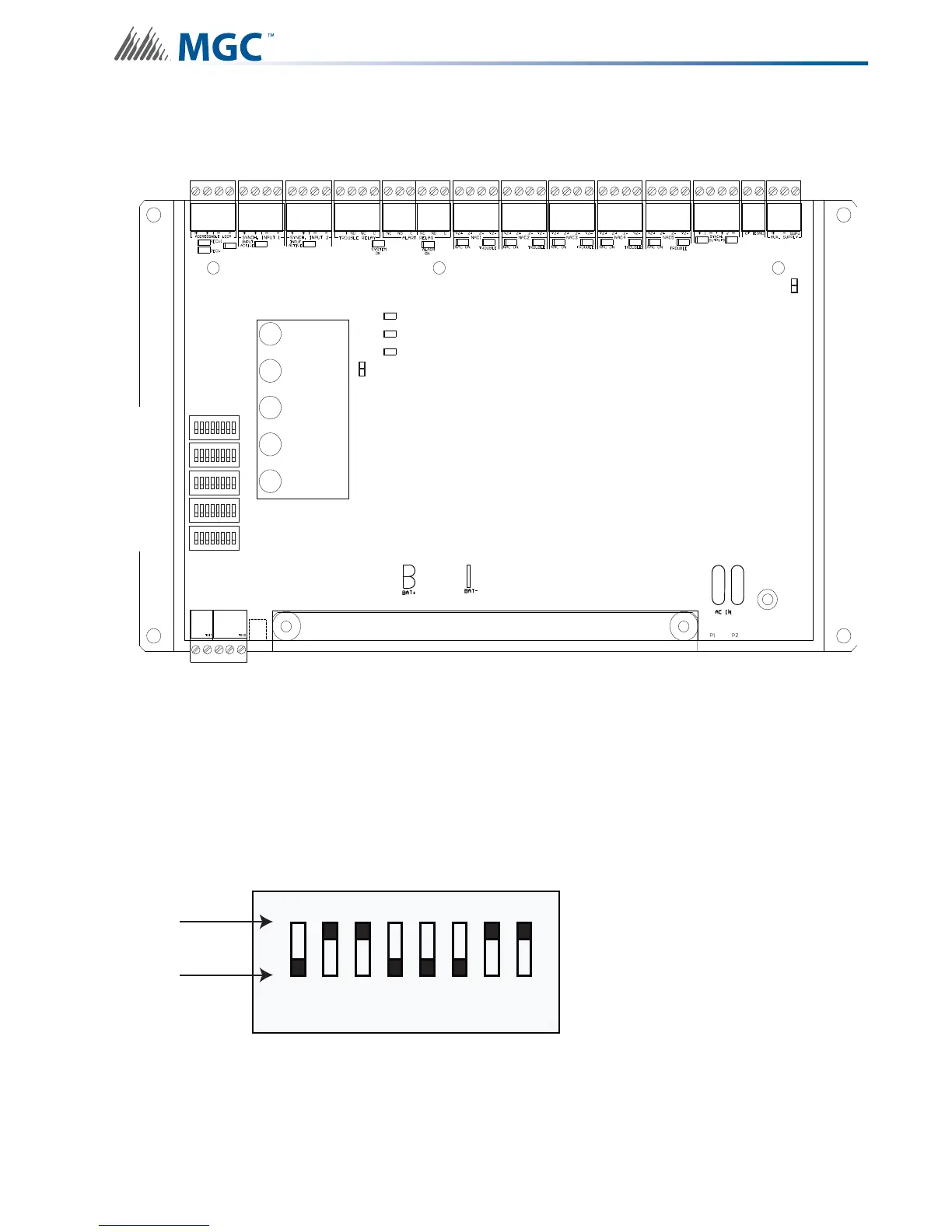
6.1 DIP Switches
The following diagram displays the five DIP switches used by the INX-10A.
6.1.1 Using the DIP switches
Configuring the INX-10A is done with 5 banks of DIP switches. They are named SW1, SW2,
SW3, SW4 and SW5. Each bank has 8 switches, numbered 1 to 8. Flipping a switch up places
it in the ON position. For the purposes of the configuration tables ON = 1 and OFF = 0. For
an illustration of the DIP switch settings see Figure 12.
Figure 12 DIP switch positions
1
8
1
8
1
8
1
8
1
8
POWER ON
ADD. LINE
ACTIVITY/
ALARM
COMMON
TROUBLE
CPU FAIL
BATTERY/
CHARGER
TROUBLE
P
DIP SW1
DIP SW5
DIP SW4
DIP SW3
DIP SW2
ACK.
BUTTON
1 2 4 8
0
1
ON
OFF
3
5 6 7
0-1-1-0-0-0-1-10-1-1-0-0-0-1-1