97
Appendix A - Specifications And Features
10.0 Appendix B - Power Supply & Battery
Calculations
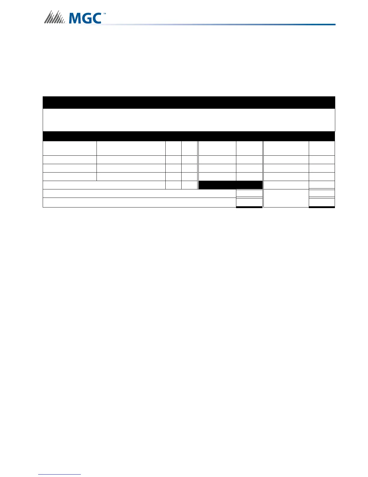
Use the form below to determine the required Main Chassis and Secondary Power Supply (batteries).
Total Current Requirement
ALARM (B)______ Amps.
Battery Capacity Requirement
([STANDBY (A)______ ] X [(24 or 60 Hours)___ ]) + ([ALARM (B)______ ] X [*Alarm in Hr.] _____) =
(C)______AH
Battery Selection
Multiply (C) by 1.20 to derate battery.
Batteries BA-104(4AH), BA-1065(7AH) and BA-110(12AH) will fit into the INX-10A, BA-117 (18 Ah) fit in the
INX-10ADS only
*Use 0.084 for five minutes of alarm or 0.5 for thirty minutes of alarm as a multiplier figure.
IMPORTANT NOTICE
The main AC branch circuit connection for Fire Alarm Control Unit must provide a dedicated continuous power without provision of any
disconnect devices. Use #12 AWG wire with 600-volt insulation and proper over-current circuit protection that complies with the local
codes. Refer to9.0 Appendix A - Specifications And Features for specifications.
Power Requirements (All currents are in amperes)
Model Number Description Qty Standby
Total
Standby
Alarm
Total
Alarm
INX-10A Main Chassis (10 Amp) X 0.200 = 0.350 =
INX-10ADS Chassis (10 Amp) X 0.200 = 0.350 =
INX-10AC Chassis (10 Amp) X 0.200 = 0.350 =
Signal Load (bells, horns, strobes, and etc.) X
=
Auxiliary Power Supply =
Alarm
=
Total currents (Add above currents) STANDBY (A)(B)