44
Configuration
6.3 Single Stage Addressing
Address Assignments are done via DIP switch 2(SW2) which is located to the left of the Main
LED display board. The addresses for the functions are dependant upon the Base Address of
the INX Panel.
There are two types of addressing options
• Basic Reporting
• Enhanced Reporting
In addition, the addressing can be changed by having NACs configured as Power Supplies.
For further information on setting the Base Address of the INX Panel see Figure 13.
6.3.1 Single Stage with Basic Reporting Addressing
To configure the recommended base address
To configure the INX for Single Stage with Basic Reporting in a Mircom system
To configure the INX for Single Stage with Basic Reporting in a Secutron system
Attention: Ensure that the configuration is set correctly on the INX-10A DIP
switches and the Fire Panel Configuration Software.
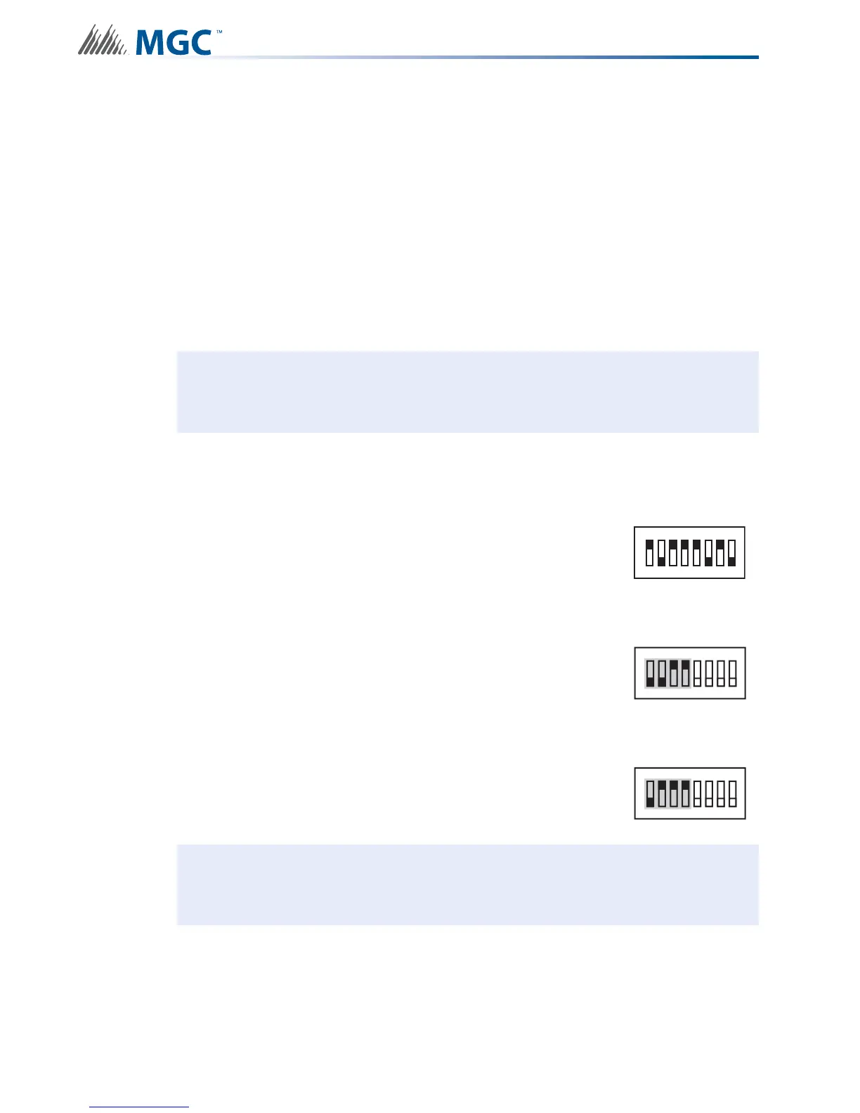
Set DIP switch SW1 as: 1-0-1-1-1-0-1-0
ON-OFF-ON-ON-ON-OFF-ON-OFF
Set DIP switch SW2-1 to SW2-4 as: 0-0-1-1
OFF-OFF-ON-ON
Set DIP switch SW2-1 to SW2-4 as: 0-1-1-1
OFF-ON-ON-ON
Attention: If NACs are configured the Evacuation Rate must be set on SW2 4-6. For
more information see Setting Alert Rates, Evacuation Rates, NAC 5
Output Functions on page 42.
SW1
1
8
234567
SW2
ON
1
8
234567
SW2
ON
1
8
234567