40
Configuration
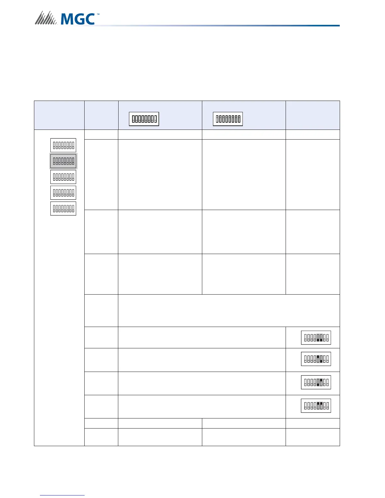
6.2.2 Setting Protocols, Reporting, Charger, Battery Installed
Use DIP switch 2 to set device protocols, enable second stage reporting, set AC fail reporting,
enabling or disabling the Charger, and if a battery is installed.
Table 6 Setting Protocols, Enabling Second Stage, Setting AC Fail Reporting, Enabling
Charger, Battery Installed
DIP switch 2 Bits
Default Setting = 0 Activated Setting = 1
Notes/
Additional
Diagrams
1 Reserve
2
Setting for Mircom FACPs
(Pro-2000)
Setting for Secutron and
other non-Mircom FACPs
For non-Mircom
panels Signal
Silence must be
configured as a
Control module
in the
proprietary
configuration
software.
3
Enable Enhanced
Reporting (AC, Battery/
Charger and Earth Ground)
*See Board LED’s for
further trouble shooting*
Free loop addresses base
+2 to base +4
Base address is
set by SW1
4 Second Stage Enabled
Free loop addresses base
+8 to base +12 or if
Enhanced Reporting is
enabled frees addresses
base +11 to base +15
Base address is
set by SW1
5-6
Configure Report Delay for AC fail
The digits below refer to the corresponding bit number
i.e. 01 means that bit 5 = 0 and bit 6 = 1 see corresponding diagram
5-6 00 = No Delay
5-6 10 = One Hour
5-6 01 = Two Hours
5-6 11 = Three Hours
7 Charger Enabled Charger Disabled
8 Battery Installed
No Battery Required and
Charger Disabled
ALL SWITCHES OFF
ALL SWITCHES OFF
1
8
2 3 4 5 6 7
ALL SWITCHES ON
ALL SWITCHES ON
1
8
2 3 4 5 6 7
ON
SW1
SW4
SW3
SW5
SW2
ON
ON
ON
ON
N
1
8
234567
1
8
234567
1
8
234567
1
8
234567
1
8
234567
SW2
ON
1
8
234567
SW2
ON
1
8
234567
SW2
ON
1
8
234567
SW2
ON
1
8
234567