41
Configuration
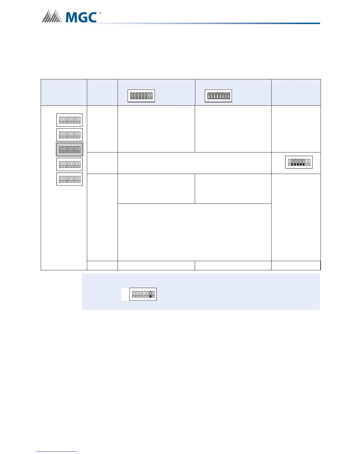
6.2.3 Charger Settings, Synchronization Settings, NAC Input Settings
Use DIP switch 3 to configure charger, synchronization and NAC Input settings.
Table 7 Charger Settings, Synchronization Settings, NAC Input Settings
DIP switch 3 Bits
Default Setting = 0 Activated Setting = 1
Notes/
Additional
Diagrams
1
Charger Cut When all
NACs activated
Charger Always “ON”
Remember
Bit 7 on DIP
Switch 2 must
be set to “OFF”
to enable
Charger
2-6 Reserve
7
Independent Mode
NAC 1 and 2 = Signals
Configured NACs = Sync
Strobes
Independent Mode
NAC 1 to 3 = Signals
Configured NAC’s = Sync
Strobes
For a
comprehensive
description of
Independent
Mode options
see 6.5
Independent
Mode
Configuration
Options on
page 74
Independent mode is active if
SW4 Bit 4-6 Evacuation Rates
is set to 010, 110, 001, 101, or 011
AND
SW5 Bit 1-3 Setting Strobe Manufacturer Type set to 100,
110, 001 or 101.
8 Synchronous Signal Master Synchronous Signal Slave
Attention: If Independent Mode is not being used SW3-7 must be set to OFF.
ALL SWITCHES OFF
ALL SWITCHES OFF
1
8
2 3 4 5 6 7
ALL SWITCHES ON
ALL SWITCHES ON
1
8
2 3 4 5 6 7
ON
SW1
SW4
SW3
SW5
SW2
ON
ON
ON
ON
1
8
234567
1
8
234567
1
8
234567
1
8
234567
1
8
234567
SW3
ON
1
8
234567
SW3
ON
1
8
234567