65
Configuration
6.4.5 Two Stage with Basic Reporting and Power Supply Output Addressing
In order to maximize the amount of addresses available, if a NAC circuit is configured as a
Power Supply, the next configured NAC Circuit is assigned the address reserved for the
previous Circuit.
Example Application
• NAC 5 configured as a Power Supply.
• INX-10A Common Trouble reporting address is 190.
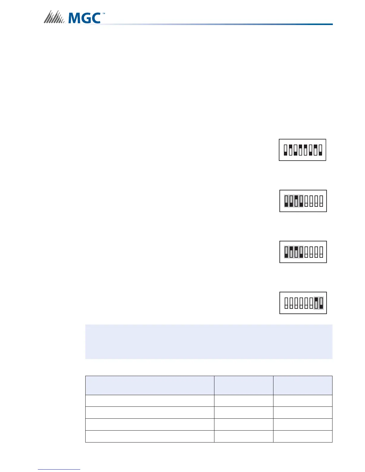
To configure the recommended base address
To configure the INX for Two Stage with Basic Reporting in a Mircom system
To configure the INX for Single Stage with Basic Reporting in a Secutron system
To configure NAC 5 as a Continuous Power Supply
Set DIP switch SW1 as: 0-1-0-1-1-0-1-0
OFF-ON-OFF-ON-ON-OFF-ON-OFF
Set DIP switch SW2-1 to SW2-4 as: 0-0-1-0
OFF-OFF-ON-OFF
Set DIP switch SW2-1 to SW2-4 as: 0-1-1-0
OFF-ON-ON-OFF
Set DIP switch SW4-7 and SW4-8 as: 1-0
ON-OFF
Attention: If NACs are configured the Evacuation Rate must be set on SW2 4-6. For
more information see Setting Alert Rates, Evacuation Rates, NAC 5
Output Functions on page 42.
Table 16 Assigning Addresses - Two Stage Application, 1 Power Supply Output
Function Address Recommended
Device Address
Common Trouble Base Address 90
Signal Silence Base Address + 1 91
Activate NAC1, return NAC1 line status Base Address + 2 92
Activate NAC2, return NAC2 line status Base Address + 3 93
SW1
1
8
234567
SW2
ON
1
8
234567
SW2
ON
1
8
234567
SW4
ON
1
8
234567