ENGLISH
Installation and User Manual
2 — 5
86-81700-00 A01
2.6 Equipment Connections
Check that the indications on the name plate located on the back of the UPS correspond to the AC-power source and the
true electrical consumption of the total load.
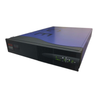
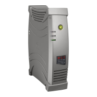
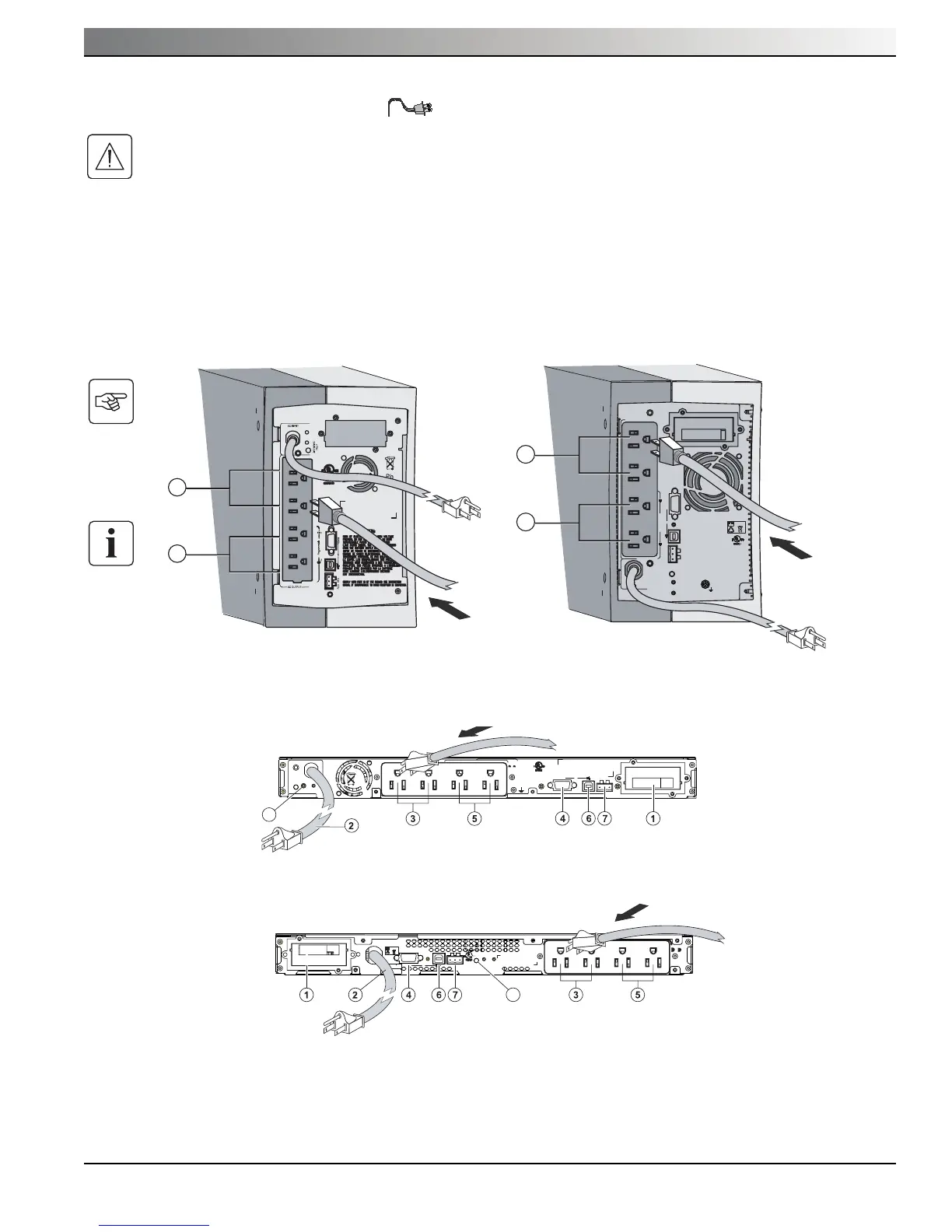
1. Connect the input power cord to the AC outlet receptacle.
2. Connect the loads to the UPS outlets as shown. It is preferable to connect the priority loads to the two outlets marked
(3) and the nonpriority loads to the two programmable outlets marked (5).
To program shutdown of outlets (5) during operation on battery power and thus optimize the available backup time, the
MGE Office Protection Systems communication software is required.
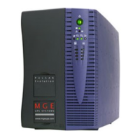
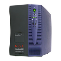
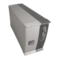
Evolution 650/850/1150 Evolution 1550
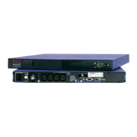
Evolution 650/850/1150 Rack
Evolution 1550 Rack