4.2 - PREPARING ELECTRIC CABLES
To prepare all connection cables, proceed as follows:
a) - Refer to fig. 7 to check the connections of the various devices to the
control unit and terminals to be used for each connection. Important
- Only devices using “ECSbus” technology can be connected to the
terminal “ECSbus”.
b) - Refer to fig. 6 to check positions of the electrical cables in the area.
Then draw a similar diagram on paper, adapting it to specific require-
ments of your system. Note - This diagram will be useful to establish
the route of the raceways for cable ducting, and to draw up a com-
plete list of the cables required.
c) - Read Table 2 to determine the type of cables to be used; then refer to
the diagram drawn above and on-site measurements to determine
the length of each cable. Caution! - No cable must exceed the
specific maximum length stated in Table 2.
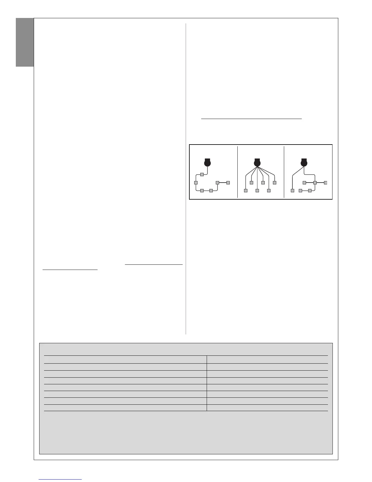
WARNING - “ECSbus” technology enables the interconnection of devices
using a single “bus” cable, with 2 internal electrical wires. Connection of
several devices can be in the configuration “cascade”, “star” or the latter
two “combined”:
––– STEP 4 –––
4.1 - PRELIMINARY CHECKS FOR INSTALLATION
4.1.1 - Establish the position of devices in the system
With reference to fig. 6 and 7, locate the approximate position for installa-
tion of each device envisaged in the system. Fig. 6 shows a system made
using this product and other optional accessories in the Mhouse range.
These elements are positioned according to a typical standard layout. The
components are:
[a] - 1 CL2S control unit.
[b] - 1 FL100 flashing light with integrated aerial
[c] - 1 pair of PH100 photocells (one TX and one RX)
[d] - 1 KS100 key-operated selector switch
[e] - 2 photocell posts
[f] - 2 limit switch stops
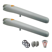
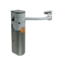
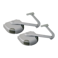
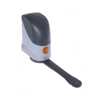
[g] - 2 electromechanical gearmotors WG1SK
WARNING! - Some of these devices are optional and may not be
present in the kit (see Mhouse product catalogue).
WARNINGS:
The fixed control devices must be positioned:
- in sight of the automation;
- far from moving parts;
- at a height of at least 1.5 m from the ground,
- not accessible by the public.
4.1.2 - Establish the position of all connection cables
Refer to the instructions in paragraph 4.2 to establish the layout of the
raceways for electric cable ducting.
4.1.3 - Ensure all equipment and materials for work are available
Before starting work, ensure that you have all equipment and materials
required to complete the work. Ensure that all items are in good condition
and comply with local safety standards.
4.1.4 - Completing the set-up work
Prepare the area for subsequent installation of the devices, completing all
preliminary work, such as:
- digging of raceways for protection ducting of electric cables (external
ducting may be used as an alternative);
- laying of protection ducting and embedding in concrete;
- sizing of all electric cables to required length (see paragraph 4.2) and
routing in protection ducting. Caution! - In this phase, do not make
any electrical connections.
Warnings:
• The hoses and ducting serve to protect electrical cables and prevent
accidental damage in the event of impact.
• When laying pipelines, take into account the risk of possible deposits of
water in the branch wells, where condensate may form in the pipelines
and the control unit with possible damage to the electronic circuits.
• Position the ends of the ducting at the points envisaged for fixture of the
various components.
4 – English
English
cascade star combined
TABLE 2 – Technical specifications of electric cables
Connection Type of cable (minimum section values) Max. admissible length
A - Power line cable 3 x 1.5 mm
2
30 m (note 1)
B - FLASH flashing light output cable 2 x 0.5 mm
2
20 m
C - Radio aerial RG58 shielded cable type 20 m (less than 5 m recommended)
D - input/output ECSbus cable 2 x 0.5 mm
2
20 m (note 2)
E - STOP input cable 2 x 0.5 mm
2
20 m (note 2)
F - OPEN input cable 2 x 0.5 mm
2
20 m (note 2)
G - Motor output M1 and M2 cable 3 x 1 mm
2
10 m
Note 1 - If the power cable is longer than 30 m, a cable with a larger section is required (e.g. 3x2.5 mm
2
) and safety earthing is necessary in the
vicinity of the automation.
Note 2 - For cables of ECSbus and those of the STOP and OPEN inputs, a single cable with multiple internal wires may be used, to combine
several connections: for example, the STOP and OPEN inputs can be connected to the KS100 selector switch with a cable of 4 x 0.5 mm
2
.
CAUTION! – The cables used must be suited to the installation environment.; for example a cable type H03VV-F is recommended for
indoor environments, and a cable type H07RN-F for outdoor environments is recommended.

 Loading...