6 – English
English
INSTALLATION: ASSEMBLY AND CONNECTION OF COMPONENTS
––– STEP 5 –––
WARNINGS
• Incorrect installation may cause serious physical injury to those
working on or using the system.
• Before starting automation assembly, make the preliminary checks
as described in STEP 3.
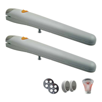
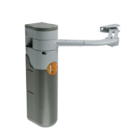
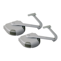
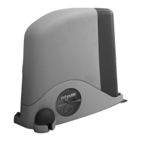
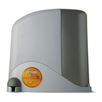
5.1 - INSTALLING THE GEARMOTOR WG1SK
To secure the gearmotor, proceed as follows:
01. Select the fixing position, observing the specifications in paragraph
3.1 “Preliminary checks”;
02. Ensure that the fixing surface is perfectly smooth, level and sufficient-
ly compact. WG1SK is not supplied with fixing devices, which must
be chosen also on the basis of the fixing surface material.
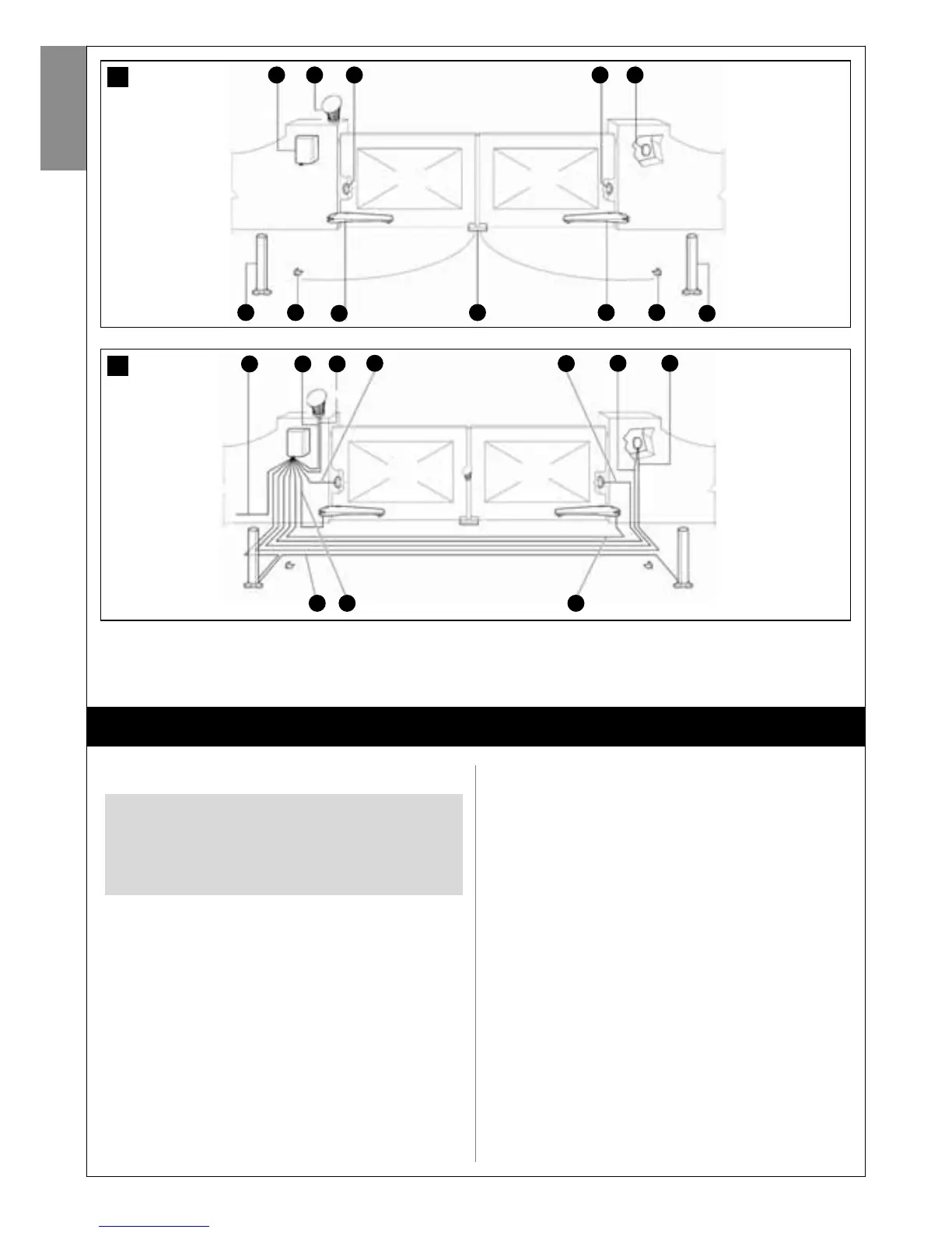
03. Lay the duct for routing the electric cable (fig. 8);
04. To construct the rear supports, assemble the two brackets and rear
plate as shown in fig. 9;
05. The brackets and rear plate can be assembled in different ways: to
IMPORTANT!
- The following assembly phases show installation of a gearmotor
model WG1SK.
- To ensure correct system operation, mechanical stops must be
mounted on the floor or wall at the maximum leaf opening and closing
points. Note - These stops are not supplied in the pack and are not
part of the Mhouse product range.
obtain the various values of “C” see fig. 10;
06. To construct the front support, assemble the bracket and front plate
as shown in fig. 11;
07. Remove the rear cover of the gearmotor by loosening the two screws
in fig. 12;
08. Move the leafs to the closed position;
09. With reference to the previously calculated position “B” (fig. 4 and 5),
place the rear support on the fixing surface, in the envisaged position;
Caution! - check the positions in fig. 15.
10. Trace the drilling points of the rear support using the support as a ref-
erence Using a drill make four holes on the surface for insertion of 4
plugs of at least 8 mm (not supplied). Fix the plate with suitable
screws and washers (fig. 13);
11. Ensure that the plate is perfectly level (the slots on the bracket enable
small corrections to alignment, as shown in (fig. 14);
12. Place the front support as shown in fig. 15;
13. Provisionally secure the front support to the leaf with a clamp (fig. 16);
14. Lift the gearmotor and insert the fork in the hole of the front support;
15. Keeping the gearmotor raised, pull to open the leaf and align the hole
on the rear plate with the hole on the gearmotor. Fix the gearmotor to
the rear support [A] using screw [B], nut [C] and washer [D] (fig. 17);
16. Tighten the nut fully down then loosen by approx. half a turn to
enable rotation of the gearmotor on its support;
17. Secure the gearmotor to the front support, tightening the screw [E]
and washer [F], then tighten the screw fully down (fig. 18);
18. Unlock the gearmotor again using the release keys (see paragraph
11.3 - User’s Guide).
19. Test a number of manoeuvres moving the gate by hand. Check that
6
a
e f h
b c d
g
c
g
f
e
7
A
D
B C
ED F
D
G G