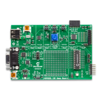
MCP2221 I
2
C Demonstration Board User’s Guide
DS50002480A-page 44 2016 Microchip Technology Inc.
5.4 PC APPLICATION REPORTS I
2
C ERRORS
If the text box corresponding to the I
2
C Communication Status label indicates an error
followed by a number, then the physical and logical setup of the I
2
C bus should be
checked. Perform the following verifications:
• Check the pull-up resistors. External I
2
C circuits connected to the MCP2221 I
2
C
Demonstration Board may have their own pull-up resistors for the I
2
C data and
clock lines, in which case, jumper J24 should be removed depending on the
resulting resistances; otherwise, J24 must be connected.
• Check for slave address conflicts. In case there are external I
2
C slaves connected
to the board, make sure there are no overlapping addresses. The list of addresses
of the devices available on the board is detailed in Section 4.3 “I
2
C Slave
Addresses of this document.
• Check the I
2
C error codes. The codes are available inside the “MCP2221
Breakout Module User’s Guide” (DS50002282, package version 06/17/2015)
available at www.microchip.com.
5.5 ISSUES PROGRAMMING THE PIC
®
MICROCONTROLLER
In case the PICkit™ 3 (or another Microchip debugger/programmer compatible to the
PIC microcontroller) is configured to provide power to the target device, but reports that
PIC16F1509 cannot be programmed, the cause may be that the PICkit 3 cannot
provide enough power to the PIC device.
In such a case, it is recommended to power the MCP2221 board externally through:
• The mini-USB connector marked as J19 (as opposed to powering from the
PICkit 3) from the PC;
or
• A USB charger that provides a constant 5V (DC) at a recommended minimum of
200 mA if the microcontroller supports this voltage level.

 Loading...