MCP2221 I
2
C Demonstration Board User’s Guide
DS50002480A-page 16 2016 Microchip Technology Inc.
2.3 JUMPERS AND CONNECTORS DESCRIPTION
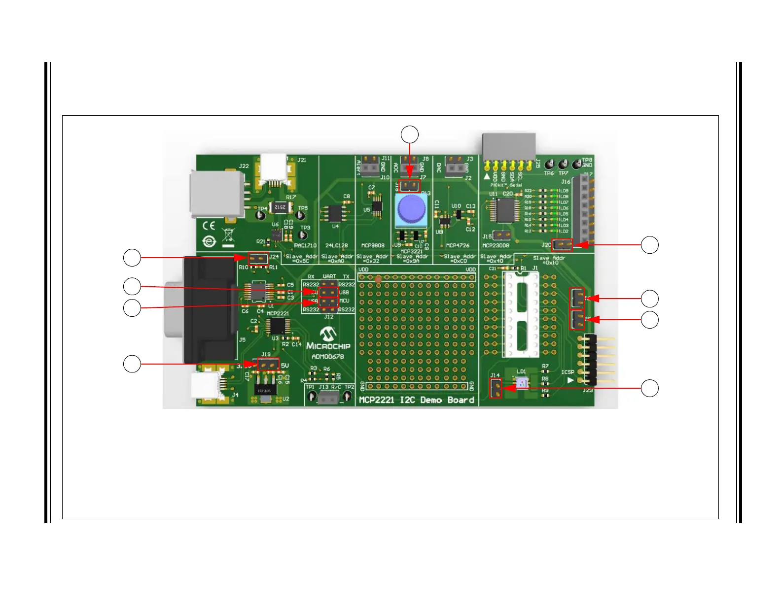
Refer to Figure 2-1 to view the default settings for the jumpers and connectors.
FIGURE 2-1: DEFAULT JUMPERS AND CONNECTORS CONFIGURATIONS
Legend:
1 = Enable potentiometer R13 for MCP3221 ADC 6 = Enable LEDs, LD2-LD9, for MCP23008 GPIO expander
2 = Enable board’s I
2
C pull-up resistors, R10 and R11 7 = Enable SDA (data) line of PIC16F1509 for I
2
C connectivity
3 = Connect UART RX of PIC16F1509 to UART TX of MCP2221 8 = Enable SCL (clock) line of PIC16F1509 for I
2
C connectivity
4 = Connect UART RX of MCP2221 to UART TX of PIC16F1509 9 = Enable RGB LED (connect to PIC16F1509)
5 = Set board voltage (V
DD
) to 5V
1
2
3
4
5
6
7
8
9