Installation and Operation
2016 Microchip Technology Inc. DS50002480A-page 17
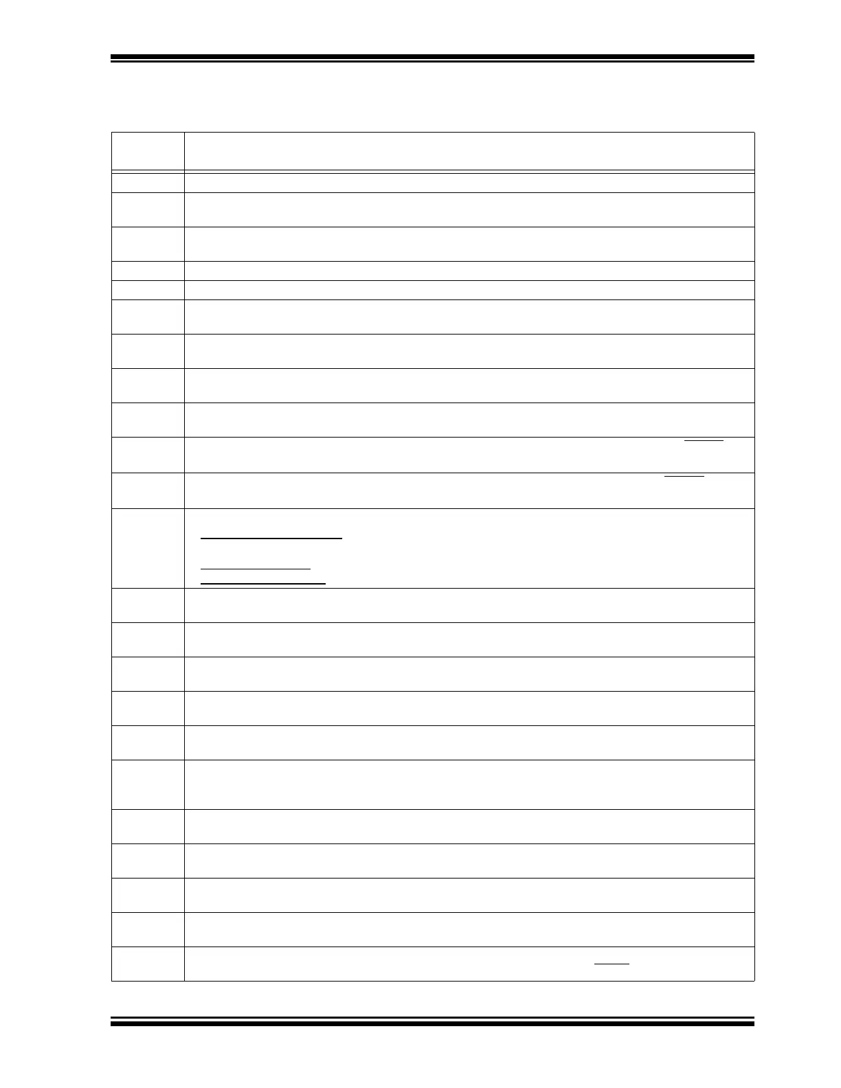
Ta bl e 2- 1 describes the functions of all the board’s jumpers and connectors.
TABLE 2-1: MCP2221 BOARD JUMPERS CONFIGURATION
Jumper
Designator
Function Description
J1 PDIP socket for PIC16F1509 microcontroller.
J2 Female connector to the MCP4726 Digital-to-Analog Converter; one pin is the DAC output and the
other connects to the ground.
J3 Male connector to the MCP4726 Digital-to-Analog Converter; one pin is the DAC output and the other
connects to the ground.
J4 Mini-B type USB female connector for power and connectivity for MCP2221 from the PC.
J5 RS-232 female connector.
J6 Jumper connecting the I
2
C SDA (data) pin of the PIC16F1509 to the board’s SDA line. This jumper is
connected by default.
J7 Female connector to the MCP3221 Analog-to-Digital Converter; one pin is the ADC custom input and
the other connects to the ground; for custom input, disconnect jumper J18.
J8 Male connector to the MCP3221 Analog-to-Digital Converter; one pin is the ADC custom input and the
other connects to the ground; for custom input, disconnect jumper J18.
J9 Jumper connecting the I
2
C SCL (clock) pin of the PIC16F1509 to the board’s SCL line. This jumper is
connected by default.
J10 Female connector for the MCP9808 temperature sensor. One pin connects to the sensor’s ALERT
pin
and the other to the ground.
J11 Male connector for the MCP9808 temperature sensor. One pin connects to the sensor’s ALERT pin and
the other to the ground.
J12 Jumper for configuring the UART/RS-232 traffic directions:
• MCP2221 to PIC16F1509: Short-circuit (RX MCU) with (TX USB), then (TX MCU) with (RX USB).
This is the default setting.
• MCP2221 to RS232
: Short-circuit (RX RS-232) with (RX USB), then (TX RS-232) with (TX USB).
• PIC16F1509 to RS232:
Short-circuit (RX RS-232) with (RX MCU), then (TX RS-232) with (TX MCU).
J13 Female connector for measuring resistances and capacitances. The ‘–’ (minus) sign indicates the
ground pin in case of measuring polarized capacitors.
J14 Jumper enabling the RGB LED LD1 that connects to the PIC16F1509. The jumper is connected by
default.
J15 Jumper allowing the possibility to connect the interrupt pin of the MCP23008 I/O expander to pin RA2 of
the PIC16F1509. The jumper is not connected by default (not populated).
J16 Female connector to the eight I/O pins of the MCP23008 I/O expander. When using the connector,
consider disabling the LEDs connected to the I/O pins by removing jumper J20.
J17 Male connector to the eight I/O pins of the MCP23008 I/O expander. When using the connector,
consider disabling the LEDs connected to the I/O pins by removing jumper J20.
J18 Jumper connecting the potentiometer R13 to the ADC input pin of the MCP3221 DAC. Disconnect
jumper to allow custom voltage measurements via connectors J7/J8. The jumper is connected by
default.
J19 Jumper for selecting the voltage level (V
DD
) of the board: connect left hand side and middle pins for
3.3V or middle and right hand side pins for 5V. The default setting is for 5V.
J20 Jumper enabling LEDs LD2-LD9 that are connected to the I/O pins of the MCP23008 I/O expander;
consider removing it if using connectors J16 and J17. The jumper is connected by default.
J21 Mini-B type USB female connector used for measuring current, voltage and power with the PAC1710.
This side goes towards the USB voltage source, such as a PC.
J22 A type USB female connector used for measuring current/voltage/power with the PAC1710. Connect
the USB device (load) through this jumper.
J23 In-Circuit Serial Programming™ (ICSP™) connector for the PIC16F1509, compatible with the
PICkit™ 3 debugger/programmer; the white triangle indicates the first pin (MCLR
/V
PP
).