Testing Board Features
2016 Microchip Technology Inc. DS50002480A-page 21
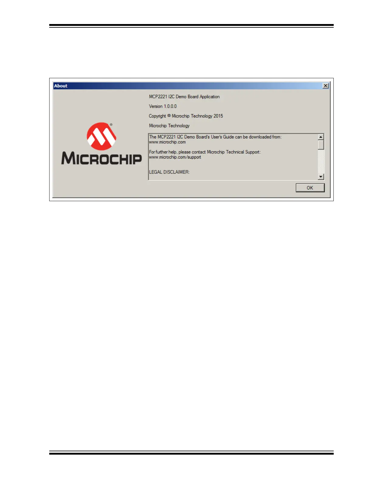
3.2.5 The About Button
Click the About button to open a window that contains information on the application’s
version and legal disclaimers. Click the OK button to close the window.
FIGURE 3-3: THE ABOUT WINDOW
3.3 FEATURE TABS
The left panel of the application contains nine tabs that allow the user to explore all the
board’s features:
• Measure R, C
• Measure USB Power
• Measure Temperature
• Read/Write EEPROM
• Read ADC
• Configure DAC
• GPIO Expander
• RGB LED Notifications
• UART Communication
Each tab displays a dedicated setting area when selected.
3.3.1 Measure R, C Tab
Capacitance is determined by measuring the capacitor’s charging time. In case of large
capacitors, the charging time is software limited to 10 seconds, after which, a
mathematical formula is applied to determine the approximate capacitance. The
charging current is provided by a digital output pin of the MCP2221 board and limited
by a 470 kΩ resistor. The Measure R, C tab also generates a charging graph for the
capacitor, as well as an indicator of its voltage.
Resistance is determined by placing the unknown resistor in series with another known
one, thus creating a voltage divider where relative voltage values are sufficient to
calculate the resistance.
Prior to performing measurements, the pins must be correctly placed in the connector
marked with J13 or use the test points, TP1 and TP2.