MCP2221 I
2
C Demonstration Board User’s Guide
DS50002480A-page 22 2016 Microchip Technology Inc.
3.3.1.1 TAB OPERATION
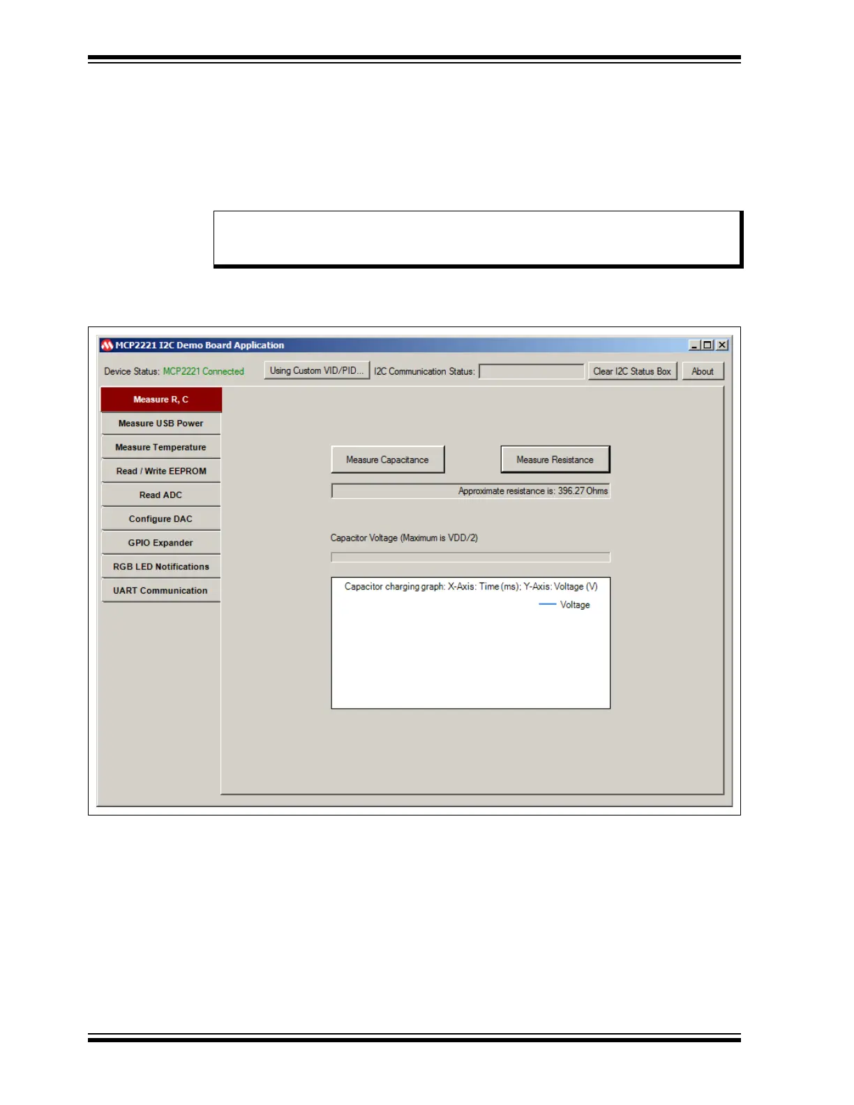
To measure a resistor or capacitor, select the Measure R, C tab.
• Click the Measure Resistance button to measure the resistance. The system
displays the approximate resistance and a capacitor charging graph.
• Click the Measure Capacitance button to measure capacitance. The system
displays the approximate capacitance and a capacitor charging graph.
Figure 3-4 shows an example of measuring resistance.
FIGURE 3-4: MEASURING RESISTANCE
3.3.1.2 CONSIDERATIONS AND WARNINGS
• The minimum supported values are around 10Ω for resistors and 40 nF for capacitors.
• To maintain a certain level of accuracy, the maximum recommended values to
measure are ~1 MΩ for resistors and 470
µ
F for capacitors.
• The measurement accuracy may be, in some cases, of about ±10%, therefore the
MCP2221 I
2
C Demonstration Board Kit is not recommended for precision
measurements.
• For both capacitor and resistance measurements, voltages are generated by
digital output pins and measured using the analog input pins of the MCP2221 I
2
C
Demonstration Board.
Note: In case of a polarized capacitor, make sure the pins are correctly placed –
the ‘+’ (plus) and ‘–’ (minus) signs on the board must be next to connectors,
J13 and TP2.