Testing Board Features
2016 Microchip Technology Inc. DS50002480A-page 23
3.3.2 Measure USB Power Tab
The Measure USB Power tab allows users to perform current, voltage or power
measurements of a USB device.
Prior to measuring the current/power of the USB device, make sure that:
• The load to be measured (for example a USB mouse) is connected to the
MCP2221 board’s USB socket marked with J22
• The power source (such as the PC) is connected to the mini-USB socket marked
with J21
3.3.2.1 TAB OPERATION
Users can determine what measurements the system should perform by selecting at
least one of the following check boxes: “Chart Voltage”, “Chart Current” or “Chart
Power”.
The “Show Numbers” check box determines whether numerical values for voltage,
current and power will also be indicated in real time inside its corresponding text box.
If the check box is selected, current and power will be indicated in real time.
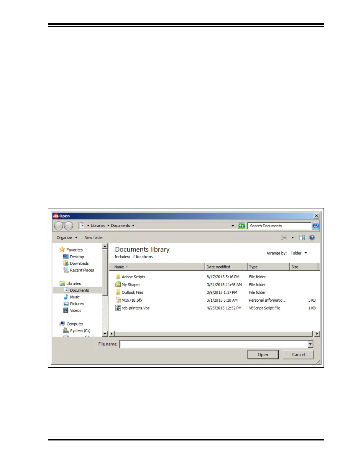
Generated data can be saved using the “Log into .CSV File …” check box. When the
check box is selected, the Open window opens to allow users to select the .csv file or
create a new document, where the measured data can be logged. Figure 3-5 depicts
this action.
FIGURE 3-5: SELECTING A .csv FILE
It is advisable to use comma separated values for the.csv file type to be Microsoft
®
Excel
®
compatible.The .csv file is generated by the application, with four columns,
and each set of readings is placed on a row. The columns are: Data entry index,
Voltage (in Volts), Current (in Amps), Power (in Watts). Logging can be turned off by
clearing the check box.