4.7.3 Using an ICD Header
Notice: For header support, see the latest Release Notes for MPLAB PICkit 4 in MPLAB X IDE v5.25 or
greater.
All Baseline and some Mid-Range PIC microcontrollers require a special –ICD device mounted on a debug header
circuit board to enable the debugging feature. For a list of these devices and the required ICD header board part
number, see the “Processor Extension Pak and Header Specification” (DS50001292).
Each ICD header board comes with the necessary – ICD device and is used on the target board instead of the
production microcontroller. However, most header boards have an RJ-11 debug connector which requires the
AC164110 RJ-11 to ICSP
™
adapter kit to connect it to MPLAB PICkit 4.
Many Mid-Range PIC microcontrollers and all PIC18 and 16-bit PIC microcontroller devices do not require an ICD
header and can be debugged directly through the ICSP programming connections.
4.7.4 Powering the Target
These are configuration essentials:
• When using the USB connection, MPLAB PICkit 4 can be powered from the computer but it can only provide a
limited amount of current, up to 50 mA, at V
DD
from 1.2-5V to a small target board.
• The desired method is for the target to provide V
DD
since it can provide a higher current. The additional benefit
is that plug-and-play target detection facility is inherited, for instance, MPLAB X IDE will let you know in the
Output window when it has detected the target and has detected the device.
If you have not already done so, connect the MPLAB PICkit 4 to the target board using the appropriate cables (see
4.6 Connecting the Target Board). Then power the target.
4.8 Setting Up MPLAB X IDE
Once the hardware is connected and powered, MPLAB X IDE may be set up for use with the MPLAB PICkit 4 In-
Circuit Debugger.
On some devices, you must select the communications channel in the Configuration bits, for example, PGC1/EMUC1
and PGD1/EMUD1. Make sure the pins selected here are the same ones physically connected to the device.
Refer to the MPLAB X IDE Help for details on installing the software and setting up the debugger to work with it.
4.9 Starting and Stopping Debugging
Note: Refer to the MPLAB X IDE online Help for information on menu option icons.
To debug an application in MPLAB X IDE, you must create a project that contains your source code so that the code
may be built, programmed into your device, and executed as specified below:
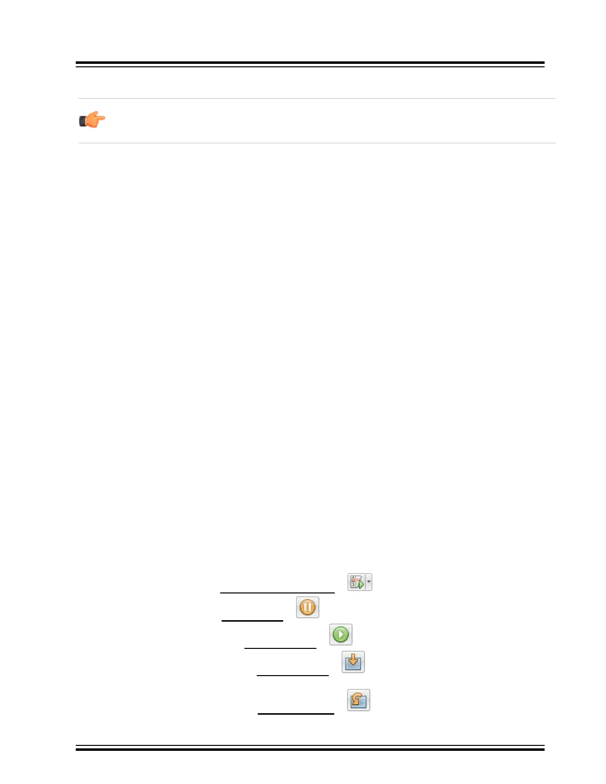
• To run your code, select either
Debug > Debug Main Project or from the Run toolbar.
• To halt your code, select either Debug > Pause or from the Debug toolbar.
• To run your code again, select either Debug > Continue or from the Debug toolbar.
• To step through your code, select either Debug > Step Into or from the Debug toolbar. Be careful not to
step into a Sleep instruction or you will have to perform a processor Reset to resume debugging.
• To step over a line of code, select either Debug > Step Over or from the Debug toolbar.
Debugger Usage
© 2020 Microchip Technology Inc.
User Guide
DS50002751D-page 21