11
STEP 6
ASSEMBLY – GRR-RIPPER ADVANCED
MODEL GR-200 (GR-100+GRAK-404)
Assembly video available online at
microjig.com/gr-assembly
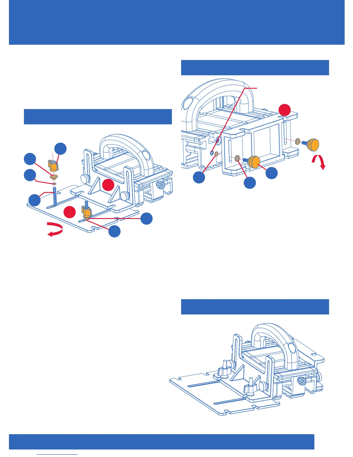
With hardware installed, snap the Stabilizing
Plate (7) into the open slots of the Balance
Support (6). Do not tighten completely.
Attach to Balance Support (6) and tighten
when desired position is achieved. It is by
design that the open slots are narrower
than the Shoulder Washer (P), so that the
Stabilizing Plate (7) will remain in place during
adjustments. The Stabilizing Plate (7) can also
be used with its straight edge facing
the GRR-RIPPER. TIP: Push the Orange
O-Ring (D) through the T-Bolt (M) all the
way down, making contact with the
Stabilizing Plate (7) before inserting the
Shoulder Washer (P) and the Thumb Knob (N).
7
6
On top of slot
N2
x2
P
x2
Orange
D
x2
M
x2
D
Reversible
The Adjustable Spacer (8) can be
attached to either side of the GRR-RIPPER
as needed. It can be used with the non-slip
pad downward to provide additional
gripping surface pressure. Lower it to
achieve two levels of pushing surfaces.
It can also perform as a “balancing device”
with the non-slip pad facing upward.
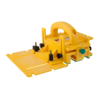
STEP 7
COMPLETED GR-200
8
Brass Insert
Adjustable
Spacer
Black
E2
x2
Figure 11
Figure 13
Figure 12
C
x2
A
x2
Reversible
ASSEMBLY
P