Brass Inserts
Side Legs
54
&
ASSEMBLY
9
ASSEMBLY – GRR-RIPPER MODEL GR-100
Assembly video available online at microjig.com/gr-assembly
INFO: If you purchased a GRR-RIPPER Handle Bridge Kit (GRHB-010), please refer to its
instruction manual for installation rst, and then resume GRR-RIPPER assembly at Step 2.
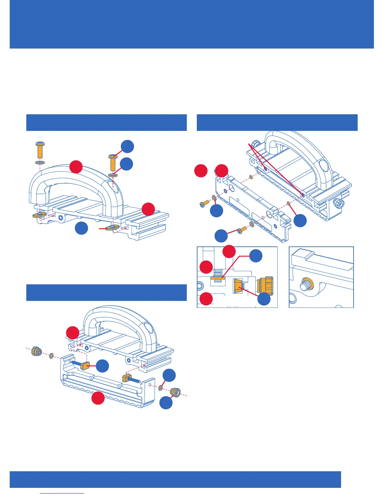
1. Install both Side Legs (4) and (5) in
the same manner on opposite sides of
the Main Body (2). 2. Insert the screws
and washers through the front screw
holes, insert the O-Rings from the back
side. See Figure 8 for detail. INFO:
If you purchased the GR-200, do not
confuse the smaller Black (C) and larger
Orange O-Rings (D).
STEP 3 & 4
Handle
1
Main Body
2
3
2
1
G
x2
Assemble Handle (1) to the top slots of
Main Body (2).
STEP 1
Close-up view with
Handle and Center Leg
installed on Main Body
Close-up of O-Ring
embedded in
counter-bore
Figure 5 Figure 7
Figure 8
Figure 6A
1. Attach mounting hardware to Center
Leg (3). 2. Assemble Center Leg (3) to the
end slots of Main Body (2) (see Figure 6A).
STEP 2
x2
B
x2
K
L
x4
G
H2
x4
C
Main Body
2
3
Center Leg
F2
x2
x2
H2
Figure 6
x2
A
x4
A