8 M32 DIGITAL CONSOLE User Manual
Main
(6) SEL Button
Press to select the Main bus for editing.
(7) COMP
The COMP indicator will illuminate when compression is being applied to
the stereo output mix.
(9) CLR SOLO Button
Press to clear all sources assigned to the solo bus.
(10) SOLO Button
Press to solo the main bus.
(11) Scribble Strip
Customisable information relating to the main bus are displayed here.
(12) MUTE Button
Press to mute the main bus.
(5) Fader
Use the MIDAS PRO Fader to adjust the output of the main bus.
(12) MUTE Button
Press to mute the main bus.
(5) Fader
Use the MIDAS PRO Fader to adjust the output of the main bus.
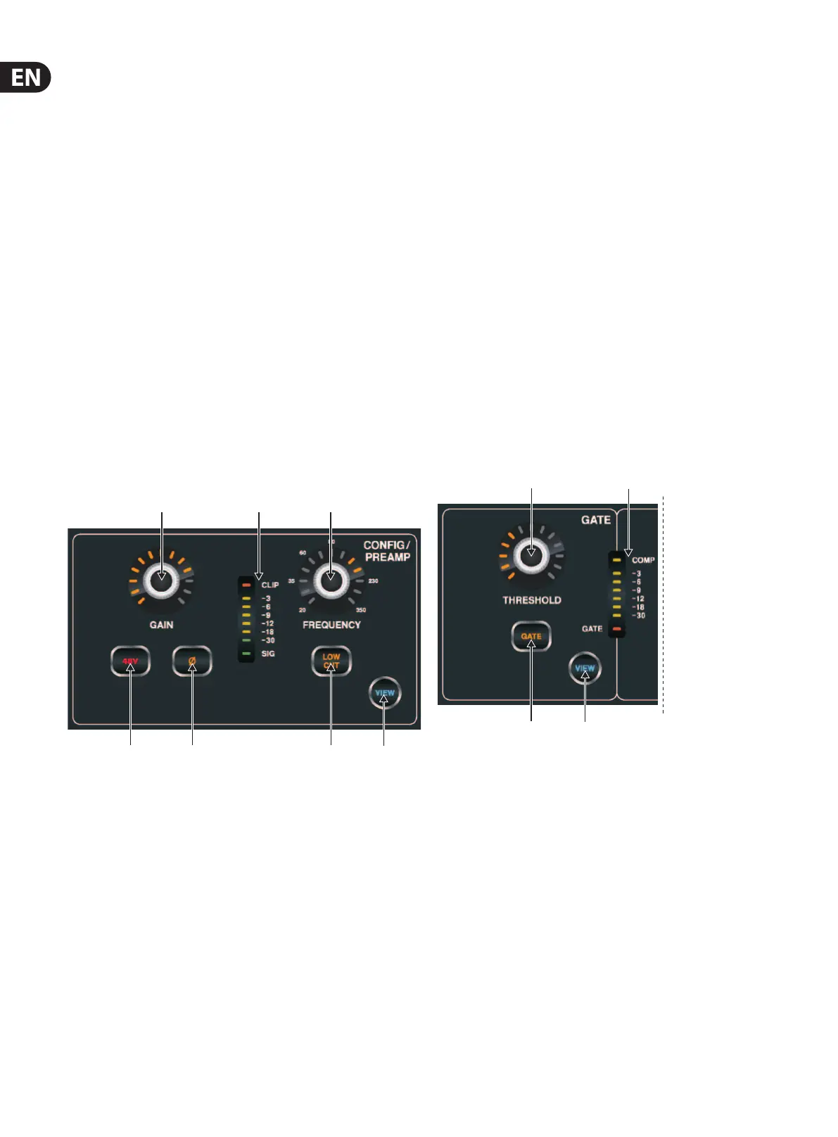
1.3 Cong/Preamp
(1) GAIN Rotary Control
On a microphone preamplier, input gain varies the amount of amplication
applied to the microphone. Adjust the preamp gain for the selected channel
with the GAIN rotary control.
(2) LED Display
The LED display in the Cong/Preamp section illustrates the signal input
level for the selected channel. This is shown as a value between 0 dB and
-30dB. When there is a signal present, but below -30 dB, the SIG LED is lit.
When the signal exceeds 0 dB the CLIP LED illuminates.
Please note that, when pressing the VIEW button, the signal input level
displayed on the Main Display shows a value of between 0 dB and -60 dB.
(3) FREQUENCY Rotary Control
The FREQUENCY rotary control selects the frequency at which the low
cut lter begins to lter unwanted frequencies for the selected channel.
Thelter is engaged by pressing the LOW CUT button (see below).
Please note that the low cut lter is only available for the 32 primary
inputchannels.
(4) 48 V
Phantom power is a method for transmitting DC electric power through
microphone cables to operate microphones that contain active electronic
circuitry. It is most commonly used with condenser microphones,
thoughmany active direct boxes also use it. The technique is also used in
other applications where power supply and signal communication take place
over the same wires. Press the 48 V button to apply phantom power on the
selected channel’s physical input.
(5) Ø
An audio signal’s ‘phase’ refers to its position in a point of time along the
waveform cycle, with each cycle being 360°. Press the Ø button to reverse
the selected channel’s phase by 180°. This can be useful when using the
reverse phase function to cancel noise across more than one channel.
(6) LOW CUT
Press the LOW CUT button to engage the low cut lter for the
selectedchannel.
Please note that the low cut lter is only available for the 32 primary
inputchannels.
(7) VIEW
Press the VIEW button to access more detailed parameters on the
MainDisplay. See the section Main Display - cong for more details.
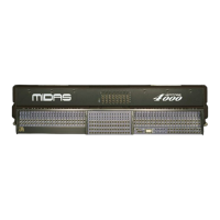
1.4 Gate
(1) THRESHOLD Rotary Control
A noise gate is a device that is used to control the volume of an audio
signal. Often used in conjunction with a compressor (see DYNAMICS),
whichattenuate signals above a certain threshold, noise gates attenuate
signals that register below the threshold. By turning the THRESHOLD
rotary control, the audio level at which the gate aects the signal can
becontrolled.
(2) LED Display
The LED display illustrates when the Gate is functioning for the selected
channel by illuminating the red GATE LED at the bottom of the display.
(3) GATE
Pressing the GATE button engages the noise gate for the selected channel.
(4) VIEW
Press the VIEW button to access more detailed parameters on the
MainDisplay. See the section Main Display - gate for more details.
(1) (2) (3)
(4) (5) (6)
(7)
(1)
(2)
(3)
(4)