28 M32 DIGITAL CONSOLE User Manual
Each of the two AES50 tabs contains the same following sets of parameters that
can be adjusted. To assign various console signal paths to the AES50 connectors,
perform the following steps:
1. Adjust the rst push encoder to select an 8-channel signal path that
will be sent to the rst eight channels of the AES50 connector’s output.
Choicesinclude:
• Local 1-8 • AES50-B 25-32
• Local 9-16 • AES50-B 33-40
• Local 17-24 • AES50-B 41-48
• Local 25-32 • Card 1-8
• AES50-A 1-8 • Card 9-16
• AES50-A 9-16 • Card 17-24
• AES50-A 17-24 • Card 25-32
• AES50-A 25-32 • Out 1-8
• AES50-A 33-40 • Out 9-16
• AES50-A 41-48 • P16 1-8
• AES50-B 1-8 • P16 9-16
• AES50-B 9-16 • Aux 1-6/Mon.
• AES50-B 17-24
2. Tap the rst encoder to connect the currently selected signal path to the
AES50 pathway.
3. Repeat the above process for the other ve sets of 8-channel AES50 outputs.
The aes50-b tab works exactly the same as the aes50-a tab, but instead selects
sources sent to the output of the console’s AES50-B connector.
xlr out
The ROUTING screen’s xlr out tab, much like the out 1-16 tab, allows the user to
patch the M32’s various internal signal paths to the 16 analogue XLR outputs that
are located on the console’s rear panel. This tab, however, allows the XLR outputs
to be patched in blocks of four, rather than individually. Also, on this screen it is
only possible to route the signal to its absolute destination, rather than choosing
the signal path. The available destinations will dier depending on the block
selected. Destinations include:
Block 1-4 / Block 9-12 Block 5-8 / Block 13-16
• Local 1-4 • Local 5-8
• Local 9-12 • Local 13-16
• Local 17-20 • Local 21-24
• Local 25-28 • Local 29-32
• AES50-A 1-4 • AES50-A 5-8
• AES50-A 9-12 • AES50-A 13-16
• AES50-A 17-20 • AES50-A 21-24
• AES50-A 25-28 • AES50-A 29-32
• AES50-A 33-36 • AES50-A 37-40
• AES50-A 41-44 • AES50-A 45-48
• AES50-B 1-4 • AES50-B 5-8
• AES50-B 9-12 • AES50-B 13-16
• AES50-B 17-20 • AES50-B 21-24
• AES50-B 25-28
• AES50-B 29-32
• AES50-B 33-36 • AES50-B 37-40
• AES50-B 41-44 • AES50-B 45-48
• Card 1-4 • Card 5-8
• Card 9-12 • Card 13-16
• Card 17-20 • Card 21-24
• Card 25-28 • Card 29-32
• Out 1-4 • Out 5-8
• Out 9-12 • Out 13-16
• P16 1-4 • P16 4-8
• P16 9-12 • P16 13-16
• Aux 1-4 • Aux 5-6/Mon
• Auxin 1-4. • Auxin 5-6/TB.
2.4 Setup
The SETUP screen oers various controls for global, high-level functions of
the M32, such as display adjustments, sample rates and synchronisation, user
settings, and network conguration.
The SETUP screen contains the following separate tabs:
global: This screen oers adjustments for various global preferences of how
the console operates.
cong: This screen oers adjustments for sample rates and synchronisation,
as well as conguring high-level settings for signal path buses.
remote: This screen oers dierent controls for setting up the console as a
control surface for various DAW recording software packages on a connected
computer.
network: This screen oers dierent controls for attaching the console to a
standard Ethernet network.
scribble strips: This screen oers controls for various aspects of the
console’s DCA groups.
preamps: This screen allows the gain on each of the individual input
channels’ preamps to be adjusted.
card: This screen selects the input/output conguration.
None of the SETUP screen’s tabs contain a secondary level of functionality, so the
UP/DOWN navigation controls do no need to be used for these screens.
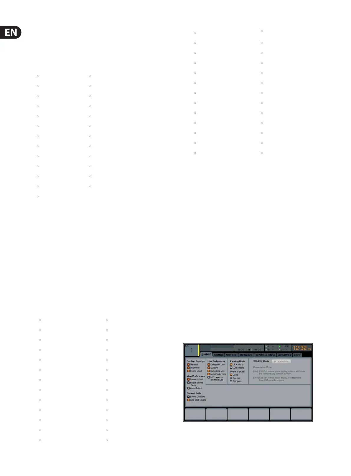
global
The SETUP screen’s global tab allows the user to adjust various global controls
of the console, such as display brightness and contrast, the panning mode used
by channels, text languages, and more.