29 M32 DIGITAL CONSOLE User Manual
To make adjustments to the global screen, perform the following steps:
1. Adjust the rst push encoder to select various console settings for pop-up
messages and assorted preferences.
2. Tap the rst encoder to turn the currently selected setting on or o.
3. Adjust the second encoder to select settings for linked console channels.
4. Tap the second encoder to turn the currently selected setting on or o.
5. Adjust the third encoder to set the console’s panning mode, which aects
how channel panning is performed in the stereo eld. The two choices are:
• LR+M: This is the default mode of the console. In this mode, channels
can be panned between left and right mix outputs, as well as assigned
to the separate mono mix bus. In this mode the Centre/Mono bus is not
aected by the pan control
• LCR: In this mode, the signal is panned from left to right. This behaviour
is emulated by the faders on the Main tab, which is more intuitive
than on other consoles. Note that in this mode, the denition of
‘mono’ changes, since the setup is no longer mono, but rather a setup
consisting of Left/Centre/Right
6. CUE: / SCN: / SNP: Toggle between these settings to control which of the
three is displayed on the external editing software.
7. Adjust the fourth encoder to set the brightness of the various LED lights on
the M32, within a range of 1-100.
8. Adjust the fth encoder to set the brightness of the Main Display, within a
range of 1-100.
9. Adjust the sixth encoder to set the contrast of the individual LCD screens
(channel display) above each input and output channel, within a range
of1-100.
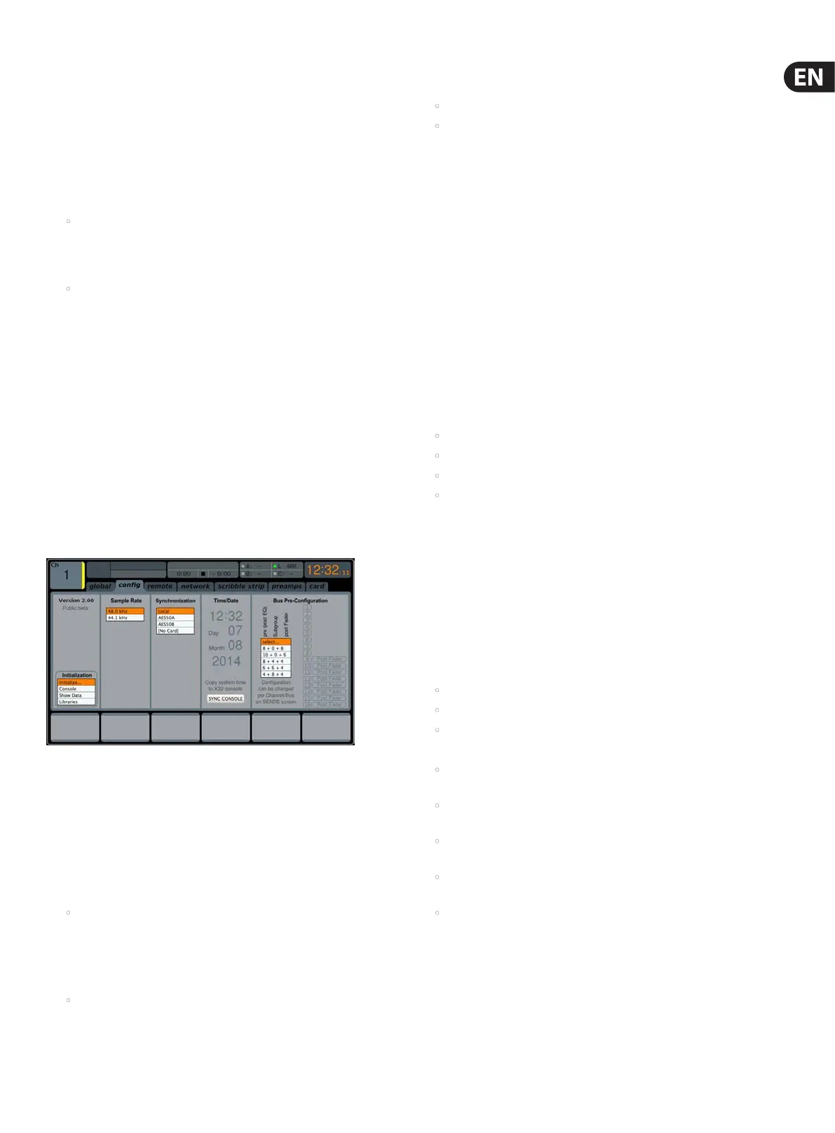
cong
The SETUP screen’s cong tab allows adjustment of various audio-related
settings, such as the console’s base sample rate and use of an internal or external
digital clock. It also oers choices for high-level global settings for how signal
path buses operate.
To adjust the various settings of the cong tab, perform the following steps:
1. Adjust the rst push encoder to select between Console, Show Data, and
Libraries for initialisation.
2. Tap the rst encoder to initialise the console back to its factory state.
• The message, “Do you really want to initialize ALL settings?”
willappear. Use the Left navigation control to cancel the operation,
orthe Right navigation control to conrm.
3. The console’s current rmware version is displayed in the rst column of the
Main Display.
• If/when a rmware update is available for the console, the user simply
needs to download the new rmware le to the root level of a USBstick.
The USB button has to be pressed while booting up, and when the
console displays “waiting for USB” on the main screen insert the
USBstick.
4. Adjust the second encoder to select the digital sample rate of the console.
Choices include:
• 44.1 kHz
• 48 kHz.
5. Tap the second encoder to assign the currently selected sample rate.
TIP: Note that the sample rate of the console will be the same sample rate for
any audio recorded to the onboard stereo USB recorder, as well as the sample
rate output by the AES/EBU connector that may get patched into an outboard
recorder. Thus, it is often benecial to select a sample rate that is appropriate for
the medium on which the recorded audio will be used.
If the programme material being recorded is audio only with no video
component, it usually makes sense to set a sample rate of 44.1 kHz. This will
ensure that any audio that is recorded is compatible with the 44.1 kHz sample
rate of commercial audio CDs.
If the programme material being recorded is audio that is meant to accompany
video, it makes sense to set a sample rate of 48 kHz. This will ensure that any
audio recorded is compatible with the 48 kHz sample rate of the various audio
formats used on a video DVD.
6. Adjust the third encoder to set the word clock synchronisation of the console
to its internal digital clock, or slave to an external digital clock. Choices for
the clock signal include:
• Internal clock
• External clock from the AES50-A port
• External clock from the AES50-B port
• Card.
Note that the graphics at the top of the screen will always display a green
LED when the console has achieved proper ‘digital lock’, from either its own
internal clock or a valid external clock.
7. Tap the fourth encoder to cycle through the dierent settings for the
console’s internal date and time settings.
8. Adjust the fourth encoder to set the value for the currently selected date/
time setting.
9. Adjust the fth encoder to select the console’s ‘Bus Pre-Conguration’.
Thissetting allows the mix bus outputs to be congured in various
combinations of:
• Pre-fader, variable output auxiliary sends
• Fixed-output subgroups
• Post-fader, variable output auxiliary sends.
Choices include:
• Eight pre-fader auxiliary sends, eight post-fader auxiliary sends,
nosubgroups
• Eight pre-fader auxiliary sends, four post-fader auxiliary sends,
foursubgroups
• Six pre-fader auxiliary sends, four post-fader auxiliary sends,
sixsubgroups
• Four pre-fader auxiliary sends, four post-fader auxiliary sends,
eightsubgroups
• Ten pre-fader auxiliary sends, six post-fader auxiliary sends,
nosubgroups.
10. Tap the fth encoder to assign the currently selected conguration.
As the conguration is selected, a display on the right-hand side of the Main
Display changes to show the currently selected conguration.