MCAC-UTSM-201707 Midea R410A T3 50Hz Top-discharge Series
104
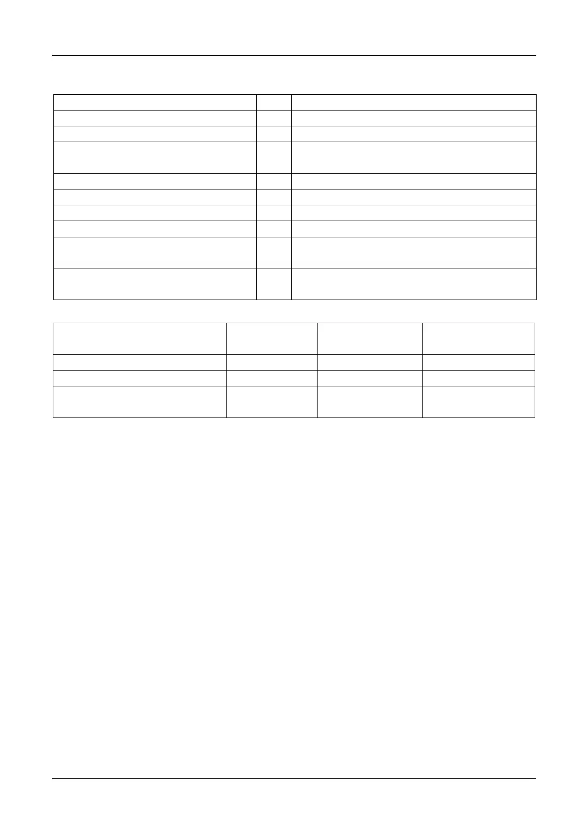
2) Accessories
Cross round head wood mounting screw
GB950-86 M4×20 (For mounting on the wall.)
Cross round head mounting screw
GB823-88 M4×25
(For mounting on the electrical switch box.)
For mounting on the wall.
For fixing on the 86 electrician box.
Switching wires for signal receiving board
For connecting the signal receiving board and
4-core shield wire.
Switching wires for wired controller signal
(If needed) For connecting the main control panel
and 4-core shielding wire.
3) Supplied assemblies on the site
Specification (Only
for reference)
Wiring tube (Insulating sleeve and
tightening screw.)
Notes to installation of wire controller
The installation manual contains information about the procedure of installing wired
controller. Please refer to indoor unit installation manual for connecting between wired
controller and indoor unit.
Circuit of wired controller is low voltage circuit. Never connect it with a standard 220V or
380V circuit or put it into a same wiring tube with the circuit.
The shield cable must be connected stable to the ground, or transmission may fail.
Don not attempt to extend the shield cable by cutting, if it is necessary, use terminal
connection block to connect.
After finishing connection, do not use megger to check the signal wire.
4) Installation procedure
1. Wired remote controller structure size figure ( Unit: mm):