45
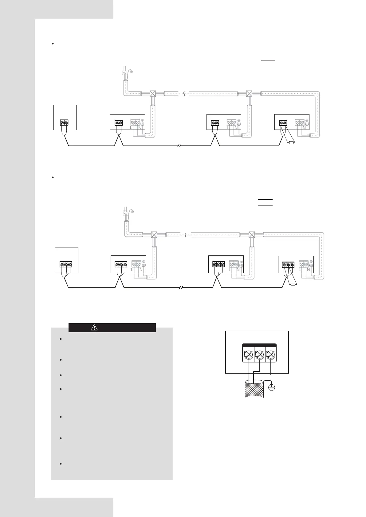
RS-485 (P Q) communication wiring configuration
P
Q
Master ODU
(n-1)# IDU
P
Q
···
2-(n-2)# IDU
1# IDU
P
Q
Breaker
L1
La
n# IDU
P
Q
Ln
Resister
Resister
N L
Power wire
Communication wire
L1+La+Ln≤1200m. Communication wiring 2*0.75mm
2
RS-485 (P Q E) communication wiring configuration
L1+La+Ln≤1200m. Communication wiring 3*0.75mm
2
Distribution box
Distribution box Distribution box
Distribution box
P
Q
P Q
P
Q
L1
La
P Q
Ln
E
E
E
E
N L
Master ODU
(n-1)# IDU
···
2-(n-2)# IDU
1# IDU
Breaker
n# IDU
Power wire
Communication wire
Figure 5.47
Figure 5.48
Figure 5.46
P
Q E
The shield layer must
be grounded
Main control board
Connect to the ODU PQE
After the last indoor unit, the communication
wiring should not route back to the outdoor
unit as this will form a closed loop.
In the last indoor unit, connect a resistor of
120 ohms between the P and Q terminals.
Do not bind the communication line,
refrigerant piping and power cable together.
When the power cable and communication
line are laid in parallel, the distance between
the two lines must be 5cm or more to
prevent signal source interference.
All IDUs in a system must be powered
through a uniform power supply so that they
can be powered on or off at the same time.
All communication lines of the IDUs and
ODUs must be connected in a series, use
the shielded wire, and the shield layer must
be grounded.
The communication wiring (P, Q, E) must
through the magnetic ring from the main
board to the IDUs.
CAUTION