46
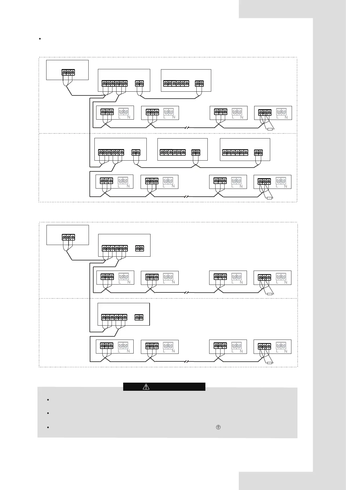
Refrigerant system 1#
IDU 1# IDU 2#
IDU (n-1)# IDU n#
Refrigerant system 2#
The H1H2 communication lines of the outdoor unit should be connected in a chain starting from the master unit to the
last slave unit. The XYE communication lines of the outdoor unit should be connected to the master unit.
The cross-sectional area of each core of the communication wiring is not less than 0.75 mm
2
, and the length must not
exceed 1200m.
Connect the shielding nets at both ends of the shielded wire to the sheet metal “ ” of the electronic control box.
CAUTION
Resister
XYE, H1H2 communication wiring
P Q
Master ODU
Slave ODU
P
Q
P Q
P Q
P Q
E
E
E
E
E
H1
H2
Centralized controller
X Y E
X Y
E
H1 H2
...
3-(n-2)# IDU
IDU 1# IDU 2#
IDU (n-1)# IDU n#
Resister
P Q
Master ODU
Slave ODU
P
Q
P Q
P
Q
P Q
E
E
E
E
E
H1
H2
X Y E H1
H2
...
3-(n-2)# IDU
Slave ODU
H1
H2
For V8 combinable series
For V8i individual series
Refrigerant system 1#
IDU 1# IDU 2#
IDU (n-1)# IDU n#
Refrigerant system 2#
Resister
P Q
Master ODU
P
Q
P Q
P Q
P Q
E
E
E
E
E
Centralized controller
X Y E
X Y
E
H1H2
...
3-(n-2)# IDU
IDU 1# IDU 2#
IDU (n-1)# IDU n#
Resister
P Q
Master ODU
P
Q
P Q
P
Q
P Q
E
E
E
E
E
X Y E
H1H2
...
3-(n-2)# IDU
Figure 5.49
Figure 5.50