Page 11
midlandusa.com
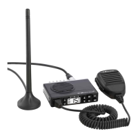
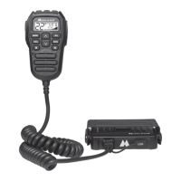
Model MXT115
Page 10
midlandusa.com
Model MXT115
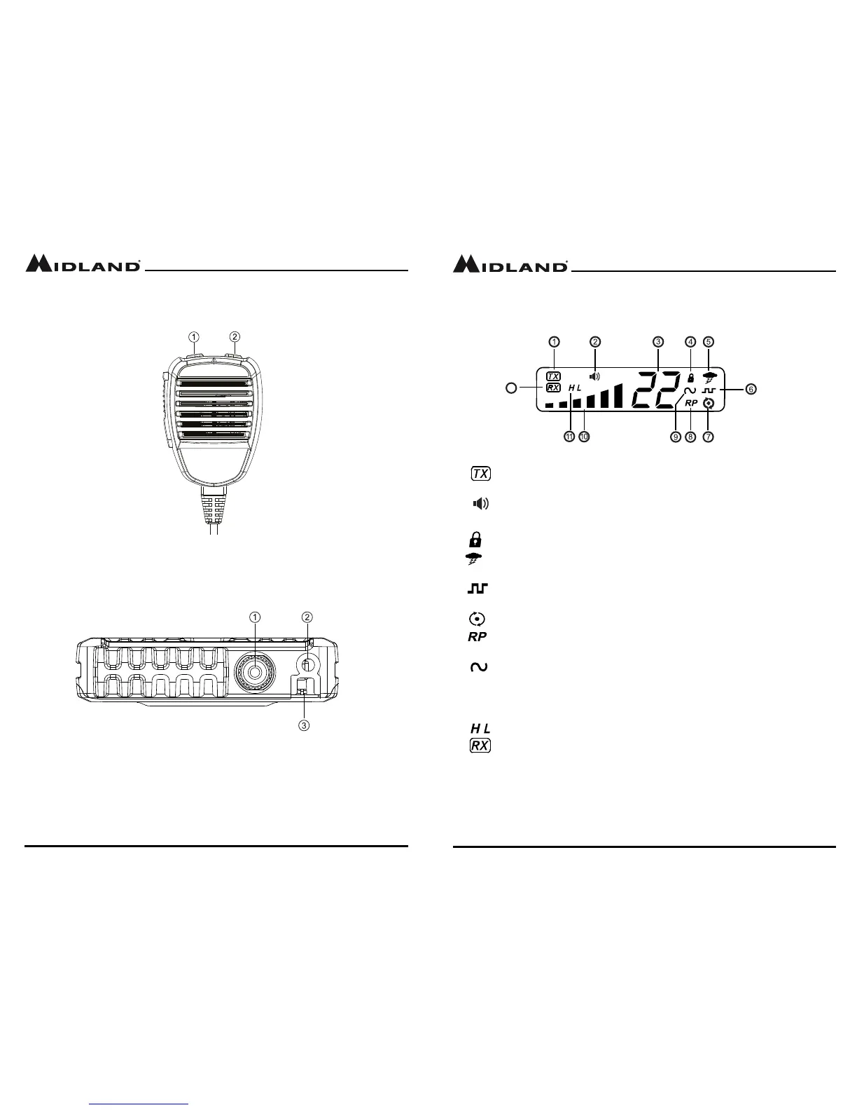
1. Transmitting Icon - Indicates the radio is transmitting to another
user.
2. Monitor Icon - Indicates when the radio is in monitor mode
3. Channel Icon - Shows the selected transmit/receive channel.
4. Key Lock Icon - Indicates KEY LOCK mode is on
5. NOAA Weather Band Icon - Indicates when the radio is in the
Weather Band mode
6. DCS Icon - Indicates a Digitally Coded Squelch Privacy Code has
been enabled for the currently selected channel
7. Scanning Icon - Indicates the “auto-scan” function is active.
8. Repeater Icon - Shows the selected transmit/recieve repeater
channel
9. CTCSS Icon - Indicates a Continuous Tone Coded Squelch System
Code has been enabled for the currently selected channel.
10. Signal Strength - Indicates the strength of the current transmit or
receive signal.
11. Transmit Power Level Icon - Indicates the transmit power setting
12. Recieving Icon - Indicates the radio is recieving a transmission
from another user.
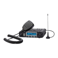
Microphone Controls
1. Channel Up
2. Channel Down
Rear Panel Connections
1. ANT Jack - SO-239 UHF connector for external antenna (included)
2. EXT SPKR Jack - 3.5mm Audio connector for optional external speaker
(purchased separately) (see Using an External Speaker for
specications).
3. 13.8V DC Cable - 2-wire DC connector for 12V DC nominal input power
connection