INSTALLATION
14 TECHNICAL DOCUMENTATION
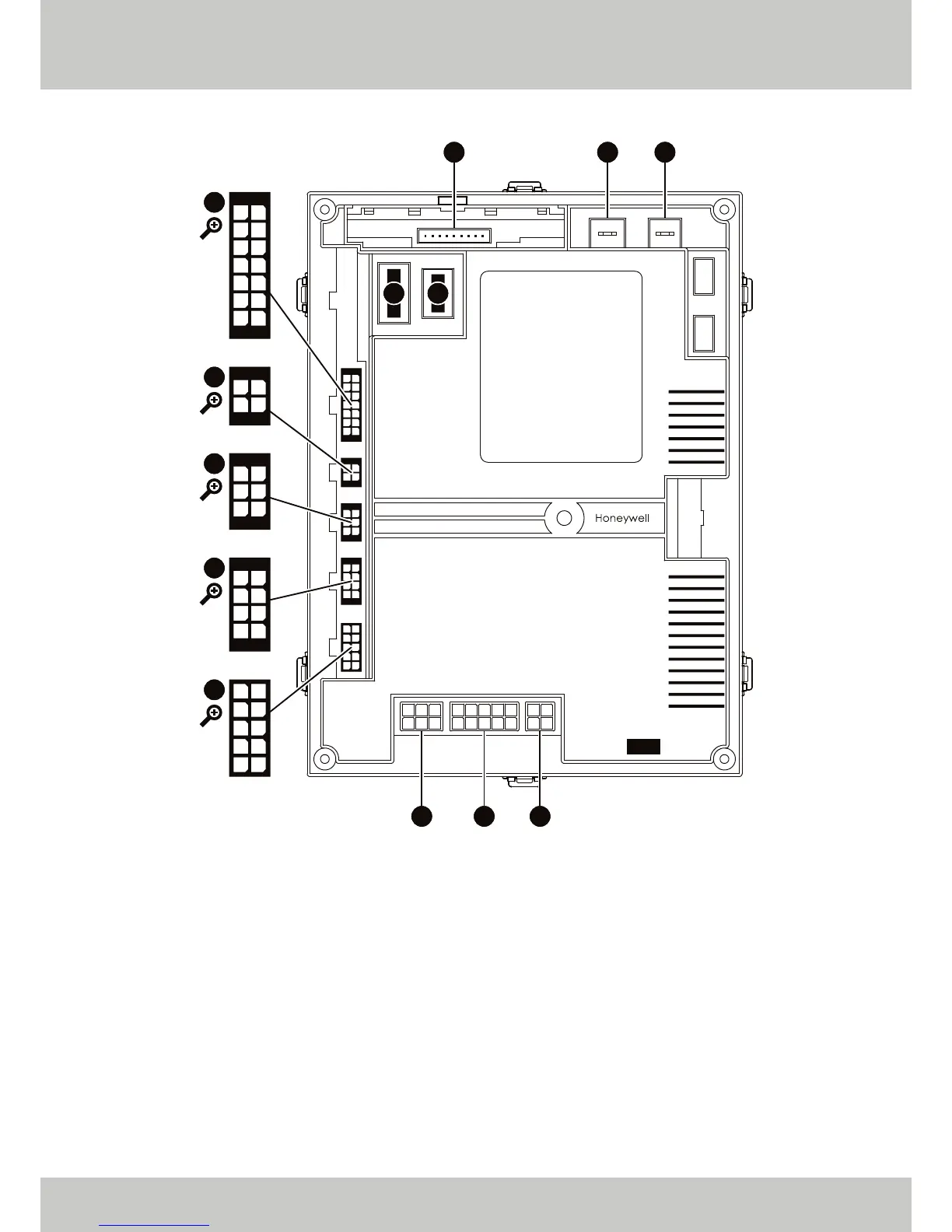
INTERNAL CONTROLS BREAKDOWN (MAIN PCB)
[1]
Used to either power additional pump or motorised valve.
[2]
Only used on ETHOS 70 models.
[3]
Only used on ETHOS 90, 110 and 130 models.
01 02 03
04 05 06
01 02 03 04 05
06 07 08 09 10
01 02
03 04
01
02
03
04
05
06
07
08
09
10
11
12
13
14
01
02
03
04
05
06
07
08
01
02
03
04
05
06
01
02
03
04
01
02
03
04
0510
09
08
07
06
X18 F00 F01
X16 X17
X13
X12
X15
X14
X11
X02 X01 X00
▲ FIGURE 02. TOP VIEW OF MAIN PCB.
• X14 Pin 01: Flue Sensor
[3]
• X14 Pin 05: Flue Sensor
[3]
• X15 Pin 01: Main PCB to Control Fascia
• X15 Pin 02: Main PCB to Control Fascia
• X15 Pin 03: Main PCB to Control Fascia
• X15 Pin 04: Main PCB to Control Fascia
• X15 Pin 05: Main PCB to Control Fascia
• X15 Pin 06: Main PCB to Control Fascia
• X02 Pin 01: Transformer
• X02 Pin 02: Transformer
• X02 Pin 05: Gas Valve Rectified
• X02 Pin 06: Gas Valve Rectified
• X11 Pin 01: AC Fan Interface
• X11 Pin 02: AC Fan Interface
• X11 Pin 04: PWM Supply
• X11 Pin 06: AC Fan Interface
• X11 Pin 07: AC Fan Interface
• X11 Pin 10: PWM Supply
• X13 Pin 01: Pressure Sensor
• X13 Pin 02: Pressure Sensor
• X13 Pin 04: DHW Sensor
• X13 Pin 05: Return Sensor
• X13 Pin 06: Supply Sensor
• X13 Pin 07: Flue Gas High Limit Switch
[2]
• X13 Pin 08: Pressure Sensor
• X13 Pin 11: DHW Sensor
• X13 Pin 12: Return Sensor
• X13 Pin 13: Supply Sensor
• X13 Pin 14: Flue Gas High Limit Switch
[2]
• X00 Pin 01: Power to Main PCB
• X00 Pin 02: Power to Main PCB
• X01 Pin 02: Pump
• X01 Pin 03: 240 V Output
[1]
• X01 Pin 04: 240 V Output
[1]
• X01 Pin 05: Fan Mains
• X01 Pin 07: Pump
• X01 Pin 08: 240 V Output
[1]
• X01 Pin 10: Fan Mains



 To Next Page