INSTALLATION
TECHNICAL DOCUMENTATION 15
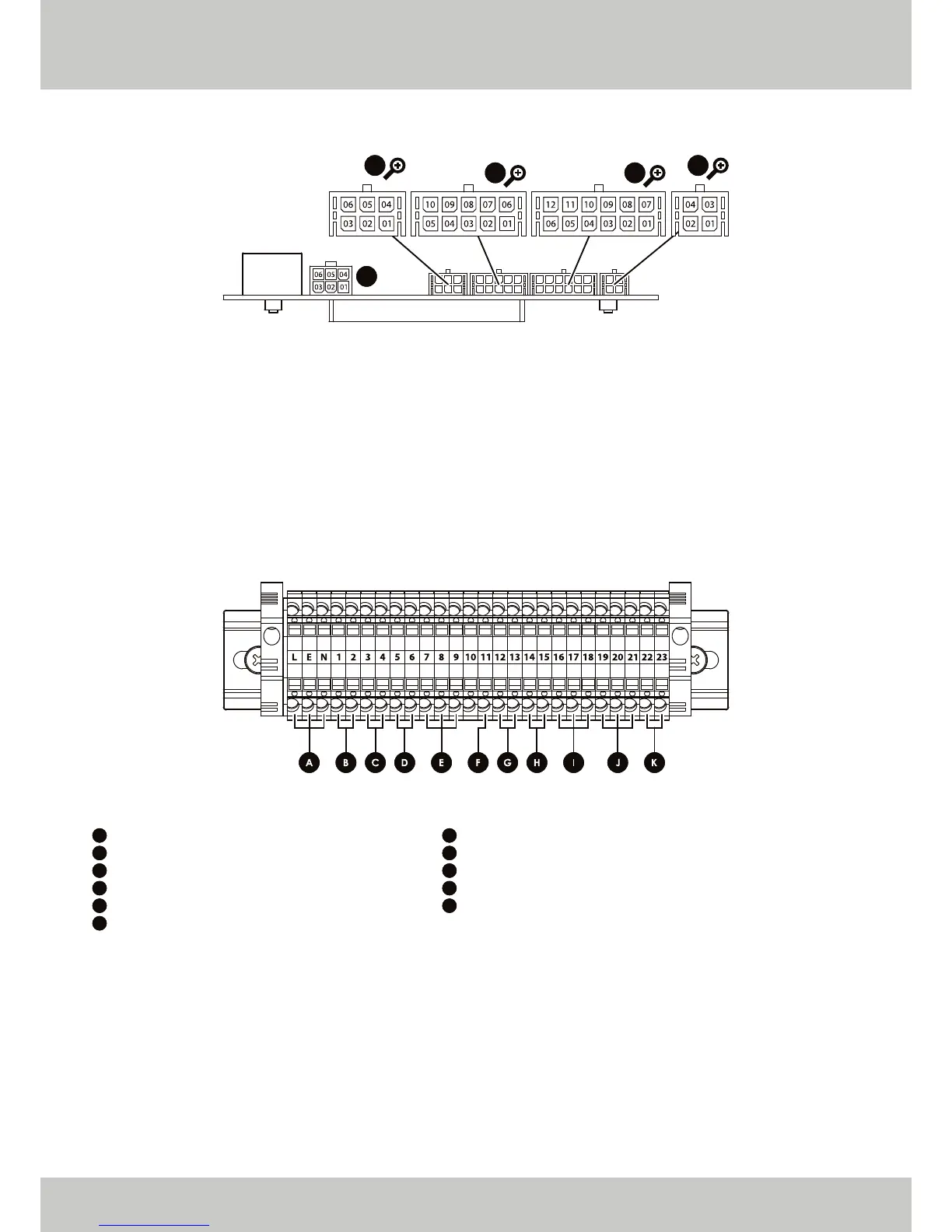
INTERNAL CONTROLS BREAKDOWN (CONTROL FASCIA)
EXTERNAL CONTROLS BREAKDOWN (DIN RAIL)
[1]
Volt Free Connection (UNDER NO CIRCUMSTANCES MUST VOLTAGE BE APPLIED TO THESE CONNECTIONS).
[2]
240 V Output in no DHW Load Condition (0.8 A).
[3]
Used to either power additional Pump or Motorised Valve (0.8 A).
[4]
240 V Output (0.8 A).
[5]
Factory fitted link, do not remove unless utilising 0 - 10 V control.
X06
X01X04
X03
X05
▲ FIGURE 03. TOP VIEW OF CONTROL FASCIA.
• X05 Pin 01: Alarm Output
• X05 Pin 02: Alarm Output
• X05 Pin 05: Reset
• X05 Pin 06: Reset
• X06 Pin 02: Communication with Slave
• X06 Pin 03: Communication with Slave
• X06 Pin 04: Communication with Slave
• X04 Pin 01: 0 - 10 V DC Input
• X04 Pin 02: OpenTherm
• X04 Pin 03: OpenTherm
• X04 Pin 04: External Sensor
• X04 Pin 05: External Sensor
• X04 Pin 06: 0 - 10 V DC Input
• X04 Pin 07: CH Cascade Sensor
• X04 Pin 08: CH Cascade Sensor
• X04 Pin 09: Room Thermostat
• X04 Pin 10: Room Thermostat
• X01 Pin 01: Control Fascia to Main PCB
• X01 Pin 02: Control Fascia to Main PCB
• X01 Pin 03: Control Fascia to Main PCB
• X01 Pin 07: Control Fascia to Main PCB
• X01 Pin 08: Control Fascia to Main PCB
• X01 Pin 09: Control Fascia to Main PCB
• X03 Pin 02: Communication with Master
• X03 Pin 04: Communication with Master
• X03 Pin 05: Communication with Master
▲ FIGURE 04. FRONT VIEW OF DIN RAIL.
A
B
C
D
E
F
Live, Earth and Neutral: Incoming Supply
Connections 1 and 2: Room Thermostat
[1]
Connections 3 and 4: External Sensor
Connections 5 and 6: DHW Thermostat
[1]
Connections 7, 8 and 9
[2]
: DHW Output
[3]
Connection 11
[4]
: Alarm Output
G
H
I
J
K
Connections 12 and 13: 0 - 10 V DC Input
[5]
Connections 14 and 15: OpenTherm
Connections 16, 17 and 18: Communication with Slave
Connections 19, 20 and 21: Communication with Master
Connections 22 and 23: CH Cascade Sensor


 To Next Page