INSTALLATION
TECHNICAL DOCUMENTATION 17
FLUE GAS DATA
The flue gas outlet is located on top of the appliance and is designed for direct connection to a corrosion
resistant flue pipe.
The flue gas discharge pipe to be used should be air tight and water tight at the joints and connections, or
should be seamless. Horizontal components in the flue pipe should be installed sloping in the direction of the
appliance (minimum of 25mm per metre).
Care should be taken when making joints to ensure that the seals are not damaged and the joints must be
sited to enable access / inspection (GasSafe TB 008 Ed. 2.1).
A direct connection to a brick chimney is not permissible unless a suitable liner is installed.
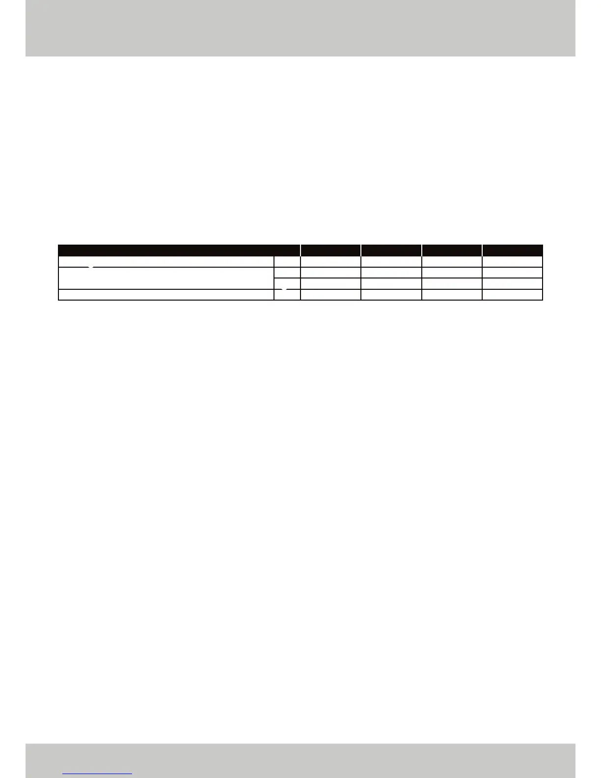
The following table gives the flue gas data for all types:
Average Flue Gas Temperature at Full Load
Maximum Permissable Flue Resistance
FLUE LENGTH
Since the boiler is equipped with a ‘premix burner’ with a fan, an over pressure is created in the boiler. This over
pressure is sufficient to overcome the resistance of the burner, the heat exchanger and the chimney.
The back pressure on the boiler depends on:
• the resistance of the flue pipe.
• the degree of cooling of the combustion gases.
• the resistance of the discharge outlet.
The degree of cooling of the combustion gases depends on the following:
• the insulation value of the flue.
• the ambient temperature.
• the flue system and outlet.
There is a maximum over pressure of around 1.4 mbar (140 Pa) for the ETHOS 70 and 90 and 2.0 mbar (200 Pa)
for the ETHOS 110 and 130 in the boiler for the flue gas discharge system.
The maximum draught permissible is 0.2 mbar (20 Pa), this should be checked with the flue warm and boilers
not firing. If the draught is above this then flue stabilisers are recommended.
CALCULATION OF DIAMETER AND LENGTH
For the calculation and control of the inner diameter of a discharge system with mechanical discharge,
please refer to the applicable national and local standards and regulations.
ETHOS 130
70
204.1
0.058
200
ETHOS 110
70
171.7
0.049
200
ETHOS 90
70
141.3
0.040
140
ETHOS 70
70
109.9
0.031
140
°C
m
3
/h
kg/s
Pa
▲ FIGURE 06. FLUE GAS DATA / LOAD 100% / FLOW TEMPERATURE 80°C / RETURN TEMPERATURE 60°C
Quantity of Flue Gas at Full Load
 Loading...