OPERATING INSTRUCTIONS
TECHNICAL DOCUMENTATION 27
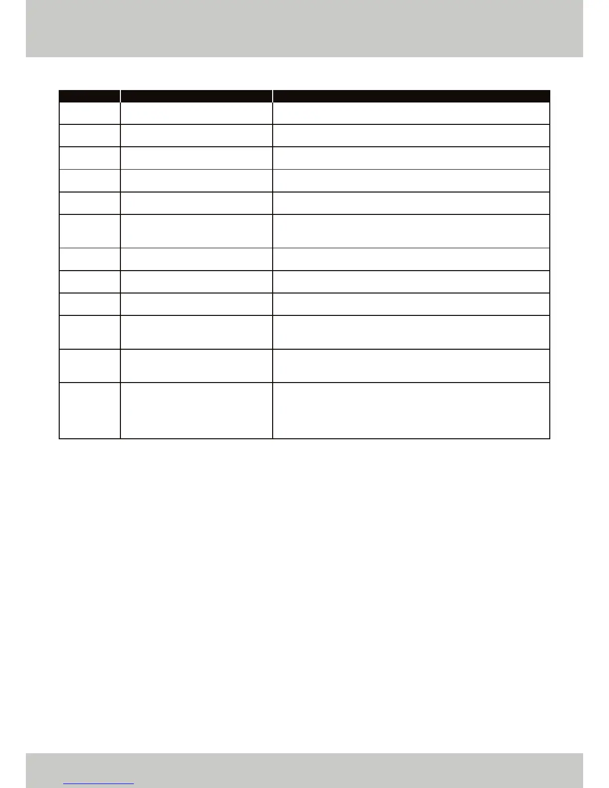
POSSIBLE ERROR CODES continued.
Several checks are included to protect the boiler and its environment. The water pressure sensor is monitored
continually for primary water condition checks, temperatures are monitored continually if they are in range,
safety times are constantly compared etc.
Any violation of (programmable) limits (and / or internal thermostat functions) will lead to an error / fault
warning condition. This condition can be shown on the display and via external controls connections. Severe
error (i.e. igniter lockout) will cause a lockout condition which can only be cleared by the reset switch on the
boiler control panel. Non severe errors / faults (i.e. sensor out of range) will reset as soon as the cause of the
problem is rectified. In case of lockout and blocking conditions, the fan will not operate and the pump will
always be on (only in a case of low water pressure will the pump be disabled).
ERROR CODE
43
44
45
46
47
80
81
95
96
97
98
99
DESCRIPTION
Return temperature sensor short
circuit.
Return temperature sensor open
circuit.
Flue gas sensor short circuit.
Flue gas sensor open circuit.
Water pressure sensor fault.
Supply and return sensor reversed.
Drift test warning.
Cascade header sensor not
connected.
Outside air sensor fault.
Cascade structure mismatch.
Communication error between
control fasciae.
Communication error between
main PCB and control fascia.
RESOLUTION
The return temperature sensor is registering a short circuit. Check the
connection to the sensor and replace the sensor if necessary.
The return temperature sensor is registering an open circuit. Check the
connection to the sensor and replace the sensor if necessary.
The flue gas temperature sensor is registering a short circuit. Check the
connection to the sensor and replace the sensor if necessary.
The flue gas temperature sensor is registering an open circuit. Check
the connection to the sensor and replace the sensor if necessary.
The boiler cannot detect the water pressure. Check the wiring to the
sensor and replace the sensor if necessary.
The return temperature sensor reading is greater than the flow
temperature sensor reading. Check for a lack of flow or reverse flow
through the boiler.
A test function is being carried out on the flow and return temperature
sensors.
The cascade header sensor has not been detected by the master
boiler. Check the wiring to the boiler and the condition of the sensor.
The boiler has detected a fault on the outside air sensor. Check for
connection to the boiler and also check the condition of the sensor.
The master boiler has detected a change in the number of connected
boilers / burners. Perform an auto detect sequence and check the
wiring and condition of other boilers / burners.
Communication between two control fasciae has been interrupted.
Check the wiring of the control fasciae, and check the fuses and
power supplies to the fasciae. Perform an auto detect sequence.
Communication between the main PCB and control fascia has been
interrupted. Check the wiring between the main PCB and control
fascia, check the fuses on the main PCB, and perform an auto detect
sequence. This may require replacement of either the main PCB or the
control fascia.
 Loading...