OM-284208 Page 31
F
Complete Parts List is available at www.MillerWelds.com
SECTION 7 – OPERATION
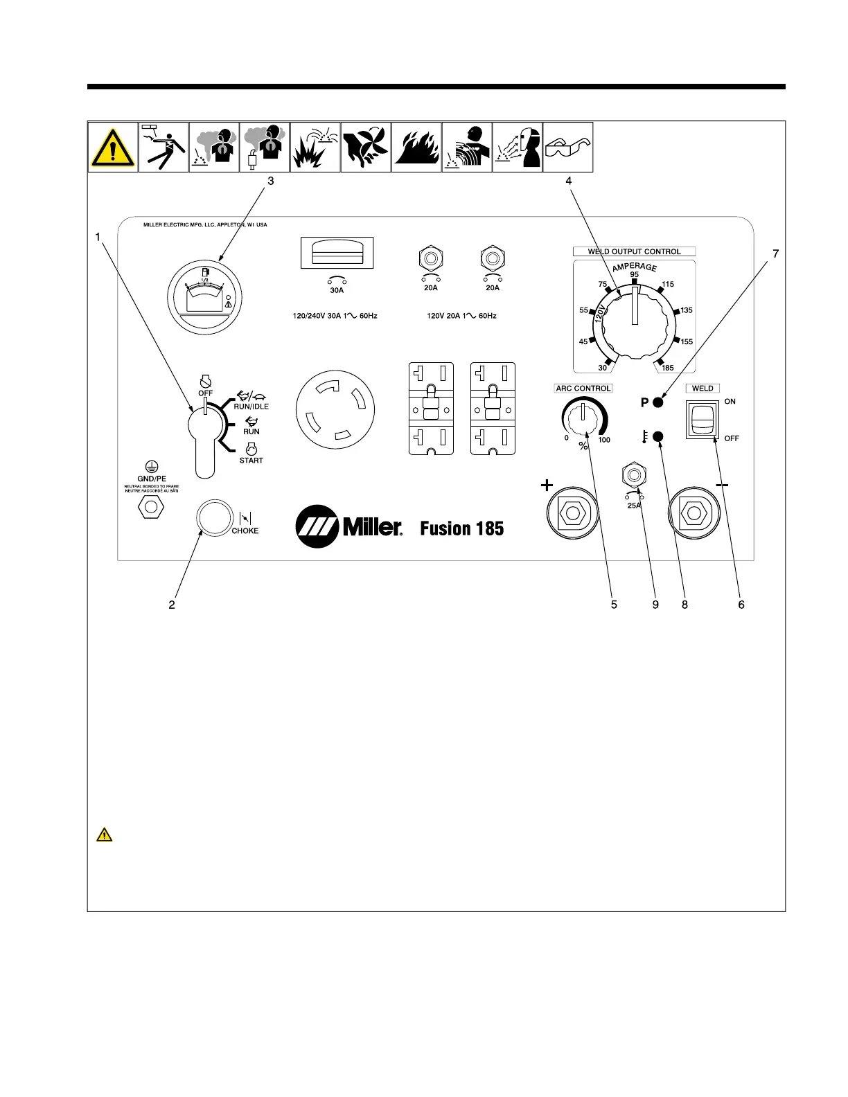
7-1. Front Panel Controls
1 Engine Control Switch
Use switch to start engine and stop engine.
In Run position, engine runs at weld/power
speed.
2 Choke Control
Changes fuel/air mixture.
To Start:
l Open fuel valve (see Section 5-6).
l Pull out choke.
l Turn Engine Control switch to start posi-
tion and hold until engine starts.
l Slowly push in choke as engine warms.
If the engine does not start, let en-
gine come to a complete stop before
attempting restart.
To Stop:
Turn Engine switch to Off.
F
Always close fuel valve after stopping
unit. Moving unit with fuel valve open
may cause carburetor flooding and
make starting difficult.
3 Engine Hour Meter/Idle Control
4 Weld Output Control
Use control to select weld amperage. Con-
trol may be adjusted while welding.
5 Arc Control
When Arc Control is set at 0% (softest),
there is no added dig current. Weld output is
constant current based on the weld
command.
When Arc Control is set at 100% (stiffest),
the dig threshold is 19.5 volts, and the maxi-
mum amount of dig current is added based
on the weld command setting. As the Arc
Control setting is reduced from 100%, the
dig threshold is lowered, resulting in less dig
current added and a softer arc.
6 Weld On/Off Switch
Use switch to turn on welder. Engine power
can be used with the weld power cable
plugged into generator or wall power.
7 Power Indicator LED
LED must be on to weld.
8 Overtemp/Fault Code LED
9 Supplementary Protector CB4
CB4 protects weld inverter when plugged in-
to generator or utility power. If supplementa-
ry protector opens, there will be no weld
output.
 Loading...