TM-273245 Page 28 S-74 MPa Plus
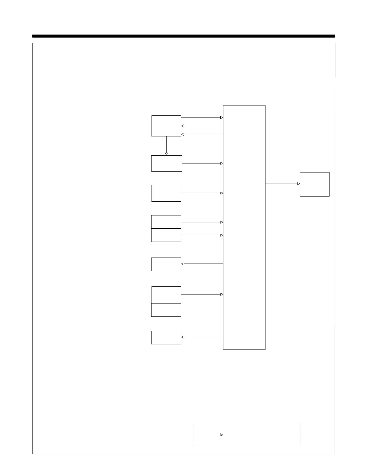
SECTION 8 − THEORY OF OPERATION
114−Pin Plug PLG12
Provides 24 volts AC input power from welding
power source, contactor control, voltage feedback,
current feedback, wfs (wirefeed speed) feedback,
and voltage control when used with a constant
voltage (CV) welding power source.
2 Power Switch S1
Provides On/Off control of 24 volts AC to wire feeder.
3 Gun Trigger Receptacle RC21
Connect gun trigger circuit to wire feeder. Gun trig-
ger circuit is isolated from the rest of the circuitry in
the feeder.
4 Jog/Purge Switch S2
• Jog − Permits jogging of wire drive motors
without energizing the weld circuit or gas valve.
• Purge − Energizes gas valves GS1 without en-
ergizing the weld circuit or wire drive motors.
5 Wire Drive Motor M1
Feeds wire at a speed set by wire speed control R1.
Motor speed is regulated by motor board PC1.
6 Tachometer Pickup Board PC8
Converts motor RPM to a pulsed feedback signal
used by motor board PC1 to regulate speed of wire
drive motor M1. 60 pulses are generated for every
revolution of drive motor armature.
7 Gas Valve GS1
24 volt AC valve provides shielding gas during the
weld cycle.
8 Motor Board PC1
• Controls wire speed by changing the pulse width
modulation
signal (wider or narrower pulses mean-
ing more or less voltage to motor) after comparing
motor speed feedback signals to wire speed com-
mand.
• Generates wfs command signal to send to
power supply.
• Motor speed is regulated using the tachometer
feedback signal.
• Energizes gas valve.
• Energizes contactor in welding power source.
• Uses current feedback from the welding power
source, through the 14−pin plug PLG12, to switch
feeder out of run−in. Run−in wire speed is a percent-
age of the weld wire feed speed.
• Converts voltage feedback signal, from welding
power source through 14−pin plug PLG12, from an
analog to digital signal to display on user interface
board PC2.
9 User Interface Board PC2
Displays wire speed, arc voltage, and help mes-
sages. The analog signals, of wire speed and arc
voltage, are converted to a digital signal by motor
board PC1. Motor board PC1 communicates with di-
gital meter board PC2 using serial communication.
Motor
Board
PC1
8
5
14-Pin Plug
PLG12
1
3
Serial
Communication
User
Interface
Board
PC2
9
Voltage Control
Contactor Control
Voltage & Current
Feedback
Power Switch
S1
24VAC
2
Gun Trigger
Receptacle
RC21
Purge Switch
S2
Jog Switch
S2
4
Tachometer
Feedback
PC8
6
Gas Valve
GS1
AC Or DC Control Circuits
7
Drive Motor
M1
PC8
 Loading...