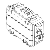
TM-273245 Page 29S-74 MPa Plus
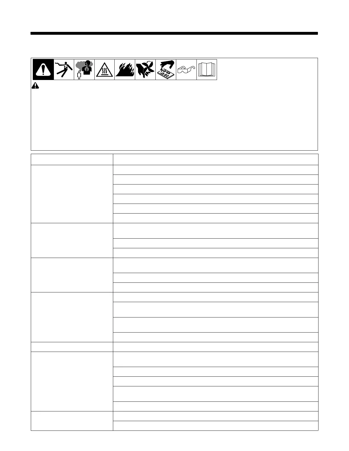
SECTION 9 − TROUBLESHOOTING
9-1. Troubleshooting Table
! Before connecting welding equipment to input (primary) power for servicing, be sure the input-power circuit protection is correct
for the welding equipment. Connect equipment to a dedicated circuit sized and fused for the rated output and duty cycle of the weld-
ing equipment you are servicing. See the Electrical Service Guide section in this manual and National Electrical Code (NEC) article
630, Electric Welders.
. Equipment serviced may need to meet additional requirements as specified in IEC60974-4, Arc Welding Equipment − Part 4: Periodic Inspec-
tion and Testing.
. See Section 9-2 for test points and values, and Section NO TAG and following for parts location.
. Use Miller Testing Booklet (Part No. 150 853) when servicing this unit.
. See the Miller Extranet for service memos that may aid in the repair of this product.
Trouble Remedy
Unit completely inoperative. Check circuit breaker on welding power source.
Check circuit breaker on wire feeder.
Check 14-pin plug and cord connections to welding power source; check welding power source.
Check continuity of Power switch S1, and replace if necessary.
Check 14-pin filter board and connections, and replace if necessary (see Section 9-10).
Check motor board PC1 and connections, and replace if necessary (see Section 9-4).
Motor does not run while pressing either
gun trigger.
Check continuity of gun trigger switch and leads. Repair or replace welding gun. See gun Owner’s
Manual.
Check trigger filter board PC8 RC18, and replace if necessary (see Section 9-11).
Check motor board PC1 RC8 and RC, and replace if necessary (see Section 9-4).
Motor does not run when Jog switch is
pressed.
Check continuity of Jog switch, and replace if necessary.
Check trigger filter board PC8 RC18 & RC19, and replace if necessary (see Section 9-11).
Check motor board PC1 RC1 & RC9, and replace if necessary (see Section 9-4).
Motor runs slowly. Check for correct line voltage.
Check push-pull gun WFS potentiometer and control cable, and replace if necessary (see push-pull gun
technical manual).
Check functionality of the encoders on the display board, and replace if necessary (if the encoders can
navigate the setup menus they are functioning properly).
Check motor board PC1 and connections, and replace if necessary (see Section 9-4).
Motor coasts after releasing gun trigger. Check motor board PC1 and connections, and replace if necessary (see Section 9-4).
Motor runs at high speed or wide open
regardless of wire speed control setting.
Check push-pull gun WFS potentiometer and control cable, and replace if necessary (see push-pull gun
technical manual).
Check tachometer board PC51 for correct feedback, and replace if necessary (see Section 9-13).
Check trigger filter board PC8 RC18, and replace if necessary (see Section 9-11).
Check functionality of the encoders on the display board, and replace if necessary (if the encoders can
navigate the setup menus they are functioning properly).
Check motor board PC1 and connections, and replace if necessary (see Section 9-4).
Gun does not seat correctly. Check to see if gun has groove for Accu-mate connection (see section 4-6).
Inspect gun power pin for damage, and replace if necessary.
 Loading...