TM-273245 Page 47S-74 MPa Plus
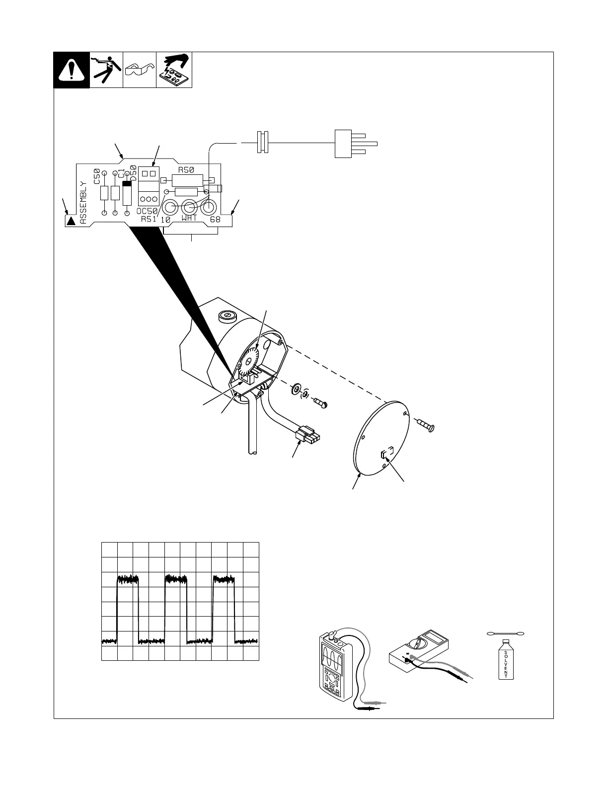
9-13. Tachometer Board PC51 Testing Information
Be sure plugs are secure before
testing.
1 Tachometer Board PC51
2 Lead Connections To Plug
PLG5
3 Plug PLG5
Pin 1 − Tachometer feedback
signal; with reference to circuit
common (pin 2). When motor is
running; frequency of pulses is
proportional to motor rpm.
Pin 2 − Circuit common
Pin 3 − +15 volts DC input
4 Encoder Disk
Remove disk, and clean using de-
natured solvent.
5 Optical Coupler OC50
Clean inside surface with cotton
swab dipped in denatured alcohol
solvent.
Center encoder disk inside OC50,
and secure with hardware.
6 Circuit Board Retaining Tabs
7 Motor End Cap
8 Weather Stripping On Inside
Of Cover
Test Equipment Needed:
237049−B / 153632-D / Ref. 137394
Pulse Output At 200 IPM;
Scope On Pin 1 And Pin 2 (Circuit Common);
Frequency (Not Voltage) Changes
0.5 ms 2 V
gnd
5
4
1
8
7
3
Tools Needed:
2
6
6
6
5
 Loading...