CHAPTER 1 - SAFETY
1
2
3
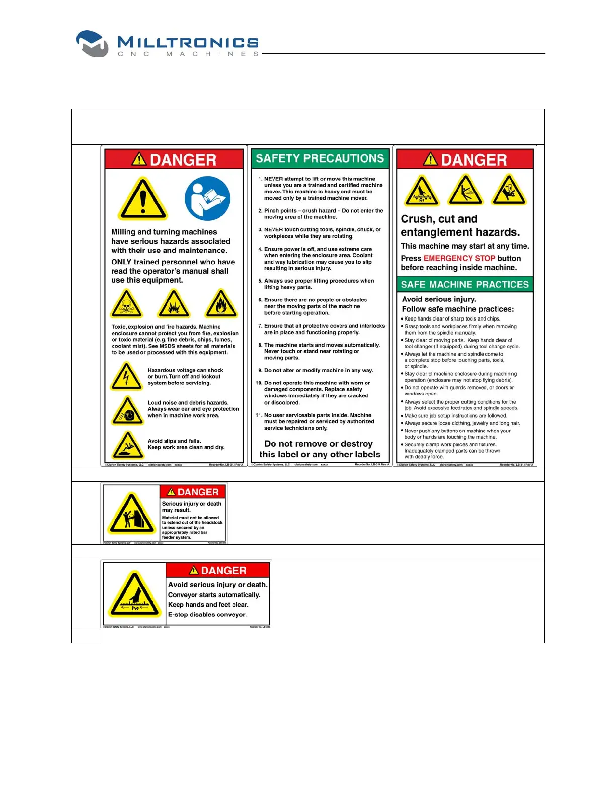
Read and understand all Safety, Operation, and Maintenance labels affixed to
the machine to ensure safet
and reliabilit
.
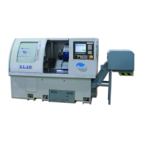
Located at headstock end near spindle
through hole.
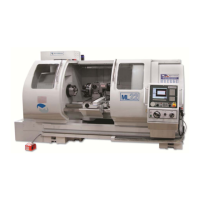
Located around hazard areas on models
equipped with chip conveyor.
9