C
HAPTER
4 - I
NSTALLATION
27
WARNING:
DANGEROUS VOLTAGES EXIST FOR THE VOLTAGE LEVEL CHECKS!
2. Check voltage levels. As stated in the Electrical Safety Rules, only qualified
personnel (as described in chapter 1) should attempt to take these measurements.
With the electrical cabinet door open, turn on the main power at the disconnect
switch. Do not reset the drives, i.e. do not push the RESET button on the front
panel.
A. Check +24 VDC. Measure between terminal blocks 12 & 22
B. Check +5 VDC. Measure between + and – V pins on the 5 VDC power
supply if present.
C. Check 110VAC on the secondary side of the 110 Volt transformer, or
between terminal blocks 1 & 2. The AC voltage must be between 110 and
125VAC.
Turn the main disconnect switch to the OFF position, powering down the machine.
Close and lock the door of the electrical cabinet.
Visually Check That Guards Are In Place
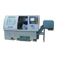
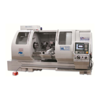
Required Guards for Lathes
Check that the enclosure door operates smoothly. CE-compliant lathes should
have a locking switch on the enclosure door.
All lathes have covers completely enclosing the spindle belts, pulleys, and/or
spindle gears.