Pellerin Milnor Corporation 29
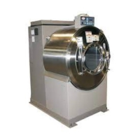
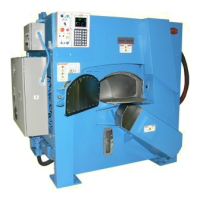
Figure 17. Compressed Air Mechanisms These are examples. Your machine can look different.
Air Operated Water Valves - Mil-
nor
®
Air Cylinder Type
Air Operated Drain Valve - Mil-
nor
®
Air Cylinder Type
Air Operated Band Brake - Mil-
nor
®
Air Cylinder Type
Air Operated Water and Steam
Valves - Angle Type
Air Operated Water Valve - Ball
Valve Type
Legend
1...Factory-set needle valves to
cause two air cylinders to
move together. Do not adjust.
2...Quick exhaust valves
3...Position indicator. Yellow
when valve is open.
4...Arrow position indicator
5...Tilt air bag
6...Air valve
7...muffler
Air Tilt Components
3.2.6 How to Do a Test of Emergency Stop Mechanisms
BNWUUH01.C05 0000335566 A.5 B.21 A.4 2/23/21 11:58 AM Released
This test applies to machines that have one or more stop mechanisms in addition to the Stop but-
ton (
). Do this test at the intervals given in the maintenance summary.
Definitions:
3-wire circuit a series electrical circuit on a Milnor
®
machine that must close before the ma-
chine can operate. If a switch in the circuit opens, machine movement stops and the operator
alarm (a buzzer and a display message) comes on. When you push the start button (
), this
closes the 3-wire circuit, which stops the operator alarm and lets the machine operate.
Routine Maintenance