© 2009 MIMAKI ENGINEERING CO.,LTD.
6.5.2 P.2
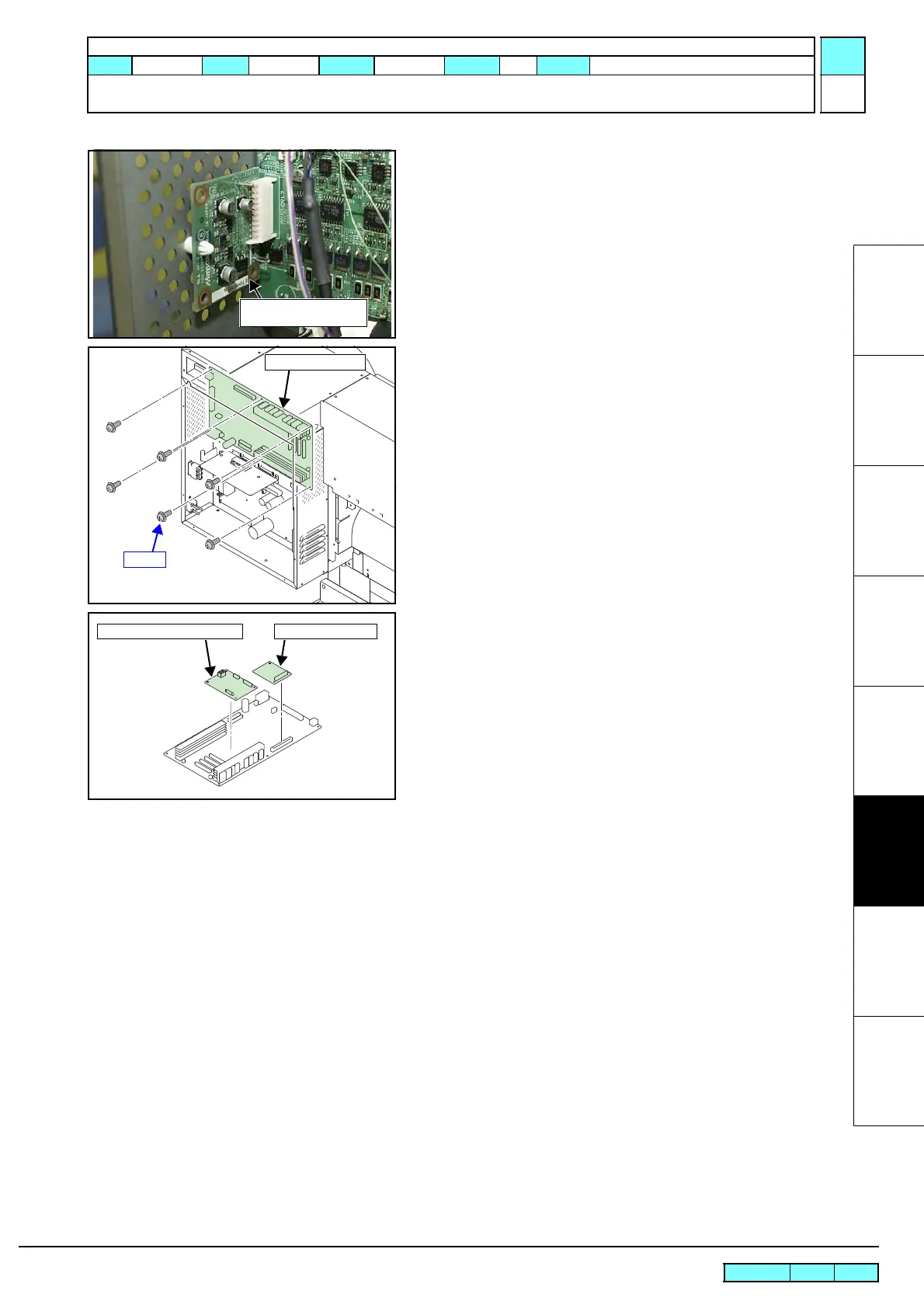
6.5.2 Main PCB Assy
1
2
3
4
5
6
7
8
4. Draw the regenerative resistance PCB assy out of the main
PCB assy.
5. Remove the main PCB assy.
6. Remove the following PCB from the removed main PCB assy.
• PRAM PCB Assy
• Cutter Driver PCB Assy
7. Reverse the disassembly procedure for reassembly.
Regenerative Resistance
PCB Assy
PRAM PCB AssyCutter Driver PCB Assy
R.1.1
Maintenance Manual > Disassembly and Reassembly > Electrical Parts > Main PCB Assy
Model CJV30/TPC Issued 2008.08.04 Revised 2008.09.17 F/W ver. 1.20 Remark
1.1

 Loading...


