© 2009 MIMAKI ENGINEERING CO.,LTD.
4.2.1 P.2
4.2.1 [HEAD ADJUST] SLANT ADJUST
1
2
3
4
5
6
7
8
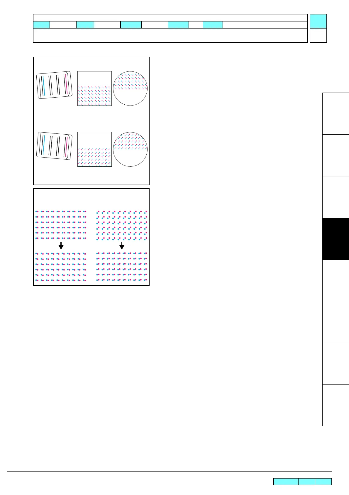
Check the slant of each column.
For the columns “b”, the relationship between the points of
impact and the slant of the head is as shown in the diagram
on the left.
For the columns “a”, the pattern is reversed.
Perform an averaging adjustment.
The standard color for each column is M for columns “a”
and c for columns “b”.
Move the adjustment lever and adjust the slant.
In the diagram on the left, the columns “b” are aligned while
the columns “a” are misaligned. In this case, move “b”
columns slightly so that the degrees of scattering of “a” and
“b” columns are equal. (=Intermediate adjustment)
<Actual Image> <Scope Image>
When tilted towards the back right
(move the adjustment lever in the
clockwise direction)
When tilted towards the front right
(move the adjustment lever in the
anti-clockwise direction)
<Adjustment Example>
Columns “b” Columns “a”
R.1.0
Maintenance Manual > Adjustment Items > Adjustment Function > [HEAD ADJUST] SLANT ADJUST
Model CJV30/TPC Issued 2008.08.04 Revised F/W ver. 1.00 Remark
1.0

 Loading...


