10
Installation
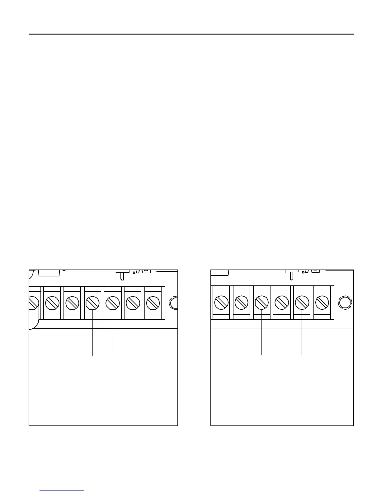
Input signal connections
Connect the incoming voltage or current signal leads to
INPUT 1 (terminal 8) and to COM (terminal 7). If the maximum
input voltage will exceed 25V, connect the signal leads to INPUT
2 (terminal 9) and to COM (terminal 7). See Figure 5 below.
Use insulated shielded wire or twisted pair for PCM4 input and
output signal leads longer than 18 inches. Connect the shielding
to earth ground at the end away from the PCM4 and trim the
exposed shielding at the PCM4 to preclude accidental grounding
of the PCM4.
Bundle the signal-carrying leads separately from the motor leads
or AC power leads.
+15
65
-15 INPUT 1
7 8
COM
9 10
INPUT 2 TP
1
R
VOLTAGE SIGNAL RANGE
0 - ±25VDC
CURRENT SIGNAL RANGES
1 - 5mA
4 - 20mA
10 - 50mA
SIG (+)COM (-)
+15
65
-15 INPUT 1
7 8
COM
9 10
INPUT 2 TP
1
R
VOLTAGE SIGNAL RANGE
0 - ±250VDC
SIG (+)COM (-)
Figure 5. Connection – Following an External Signal
COM (-)
VOLTAGE SIGNAL RANGE
0 - ±25 VDC
CURRENT SIGNAL RANGES
1 - 5 mA
4 - 20 mA
10 - 50 mA
SIG (+)
COM (-)
VOLTAGE SIGNAL RANGE
0 - ±250 VDC
SIG (+)