20
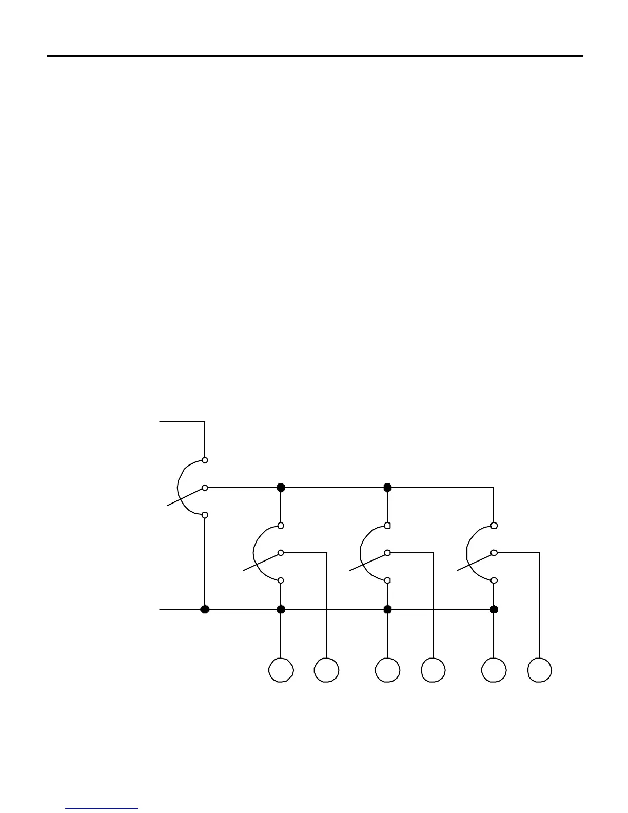
Connect one 50K ohm ratioing potentiometer across the master
input voltage signal for each dedicated PCM4 module. Wire each
ratioing pot to the input signal source potentiometer as shown in
Figure 11 below.
Master PCM4 with multiple drives following
If a PCM4 is to provide the master input voltage signal as
detailed on pages 14 - 15, dedicated PCM4s are again necessary.
Each of the PCM4s must be modified as detailed on page 19.
Ratioing potentiometers may then be wired with their CW sides
to terminal 2 of the master PCM4 and their CCW sides to
terminal 1 of the master PCM4.
Installation
107 107 107
50K 50K 50K
MASTER
INPUT SIGNAL
POTENTIOMETER
-
PCM4
#1
PCM4
#2
PCM4
#3
Figure 11. Connection – Ratio Potentiometers Multiple Follower System
MASTER
INPUT SIGNAL
POTENTIOMETER
+
50K
PCM4
#1
PCM4
#2
PCM4
#3
7 10 7 10 7 10
50K 50K
-